UML for Android Engineers
Learn how to draw UML diagrams to document your Android applications. By Massimo Carli.
Representing Abstract Classes
To see an example of an abstract class in the Poster Finder project, open the BaseFragment.kt file in the ui.screen package and look at the following code:
abstract class BaseFragment : Fragment() { // 1

  protected var navigationHandler: NavigationHandler? = null // 2

  @CallSuper
  override fun onAttach(context: Context) {
    super.onAttach(context)
    navigationHandler = context as? NavigationHandler
  }
}
This is the base class for Fragments that want to access the NavigationHandler in the hosting Activity, if any. Note how you use:
- The abstract keyword for
BaseFragment. - The protected visibility modifier for the instance variable navigationHandler.
The following class diagram describes BaseFragment and its relation with MovieListFragment, which you find in the same package:
Abstract classes in UML

A few interesting things to note in this diagram are:
- You represent the abstract class using the «abstract» stereotype above the name of the class, that’s optionally in italic.
-
navigationHandlerhas protected visibility and you represent it with the # symbol. -
MovieListFragmentis a concrete realization ofBaseFragment. As you already learned while working with interfaces, you represent this with a dotted line ending with an empty triangle.
Speaking of Fragments, here’s an interesting case to consider. It’s a great opportunity to learn how to represent static members in UML.
Representing Static Members in UML
When working with Fragments, it’s not uncommon to see code like what you find in the DisplayPosterFragment.kt file in the ui.screen package:
@AndroidEntryPoint
class DisplayPosterFragment : Fragment() {

  companion object {
    @JvmStatic
    private val MOVIE_KEY = "MOVIE_KEY" // 1

    @JvmStatic
    fun create(movie: UiMovie): DisplayPosterFragment = // 2
        DisplayPosterFragment().apply {
          this.arguments = Bundle().apply {
            putSerializable(MOVIE_KEY, movie)
          }
        }
  }
  // ...
}
In this code, you define a companion object with the:
-
MOVIE_KEYconstant to use as a key forBundlecontaining the arguments forFragment. -
static factory method
create()returning theDisplayPosterFragmentgiven the model of typeUiMoviewith the data to display.
Again, how can you represent DisplayPosterFragment in UML? Consider the following diagram:
Class Diagram – DisplayPosterFragment

In this simple diagram, there are three interesting things to note:
- You say that
DisplayPosterFragmentis aFragmentusing the custom «fragment» stereotype. This allows you to save some space, avoiding the representation of the parentFragmentclass. -
MOVIE_KEYis constant and static. You understand it’s a constant because it’s all CAPITALIZED. You then realize that it’s static because it’s underlined. - The same is true for
create(). This is a static method because it’s underlined.
The diagram ignores the fact you’re using a companion object. This depends on the detail of the information you want to represent. If you wanted to make the companion object explicit, the diagram would be like the following:
Class Diagram – Companion Objects

Here you represent the companion object as a private static variable for DisplayPosterFragment. The relation is a composition, meaning that DisplayPosterFragment is responsible for the creation of DisplayPosterFragment.Companion. It’s up to you to decide if this version gives you meaningful information.
Representing Just What You Need: Another Example
In the previous paragraphs, you saw different class diagrams and learned how to use custom stereotypes like «fragment». As said in the introduction, UML allows you to do what you think is best for improving the readability of your system. A UML diagram should be simple and small. Consider the following version of the diagram you saw earlier about MainActivity:
Class Diagram Simplified

In this diagram, you used two very useful tools to make it simpler and smaller:
- Using a lollipop notation, you’re just saying that
MainActivityimplementsNavigationHandler. This is very useful if you don’t care about the operation of the interface, or when you have used it more than once and you want to save space. The lollipop notation consists of a solid line ending in a circle without arrows. - You save a lot of space using the «activity» custom stereotype.
This is an example of how UML allows you to describe many things with a small diagram. Stereotypes are very useful in many cases.
Using Stereotypes
In the Poster Finder app, you have some classes apparently very similar that you can consider as Plain Old Java Object (POJO). Open the MovieDto.kt file in the api.dto package to get the following code:
data class MovieDto(
    @SerializedName("imdbID") val movieId: String,
    @SerializedName("Title") val title: String,
    @SerializedName("Year") val year: String,
    @SerializedName("Type") val type: String,
    @SerializedName("Poster") val posterUrl: String
)
Now open the UiMovie.kt file in the ui.model package to get this:
data class UiMovie(
    val id: String,
    val title: String,
    val posterUrl: String,
) : Serializable
The Poster Finder project doesn’t have a database. Otherwise, for instance using Room, you would have something like:
@Entity
data class Movie(
    @PrimaryKey @ColumnInfo("id") val movieId: String,
    @ColumnInfo("title") val title: String,
    @ColumnInfo("year") val year: String,
    @ColumnInfo("type") val type: String,
    @ColumnInfo("poster") val posterUrl: String
)
They are all implemented with data classes, but they have different contexts. The question now is: How do you represent all these different classes? The answer is custom stereotypes, like this:
Custom Stereotypes
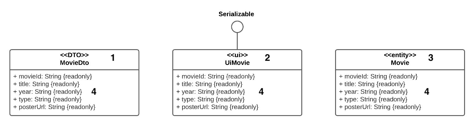
What do you want to communicate with this diagram? Besides the different properties, you’re saying that:
-
MovieDtois a Data Transfert Object (DTO). -
UiMovierepresents an object you use for the UI and it implementsSerializable. -
Movieis an entity, so it has to do with persistence. - All the properties are read only. This is a typical use of a constraint you represent using the {constraint} symbol. What the constraint is depends on the context or, for instance, the language. In this case, this means you’re using a val instead of var.
Again, it’s up to you to decide if these diagrams are necessary for understanding the code in your app. In the case of the Poster Finder app, probably not. It would be much more useful to use them in a diagram representing the relations.
Creating Dynamic UML Diagrams
The diagrams you’ve learned about so far are static, meaning they describe unchanging relationships between different items. UML also has other types of diagrams you can define as dynamic that describe how different items collaborate or communicate over time. Two very important dynamic UML diagrams like this are:
- Collaboration diagrams
- Sequence diagrams
As its name says, a collaboration diagram describes how different objects collaborate to accomplish a given task. The goal is to understand what objects communicate most so they can be put in the right place. For instance, objects communicating very frequently will probably, but not necessarily, go in the same package. This diagram helps you to understand that.
You use a sequence diagram to describe how different objects collaborate over time. As you’ll see, time is an explicit thing you represent with a vertical line.
Before describing a diagram of each type for the Poster Finder app, it’s important to note how both collaboration and sequence diagrams deal with objects and not with classes. How do you represent an object, then?