UML for Android Engineers
Learn how to draw UML diagrams to document your Android applications. By Massimo Carli.
Creating Complex Use Case Diagrams
Suppose now that every user can search for a movie poster, but only some of them can actually display the detail. You also want to represent the case where the movie isn’t found. How can you represent this in UML?
Look at the following diagram:
A Complex Use Case Diagram
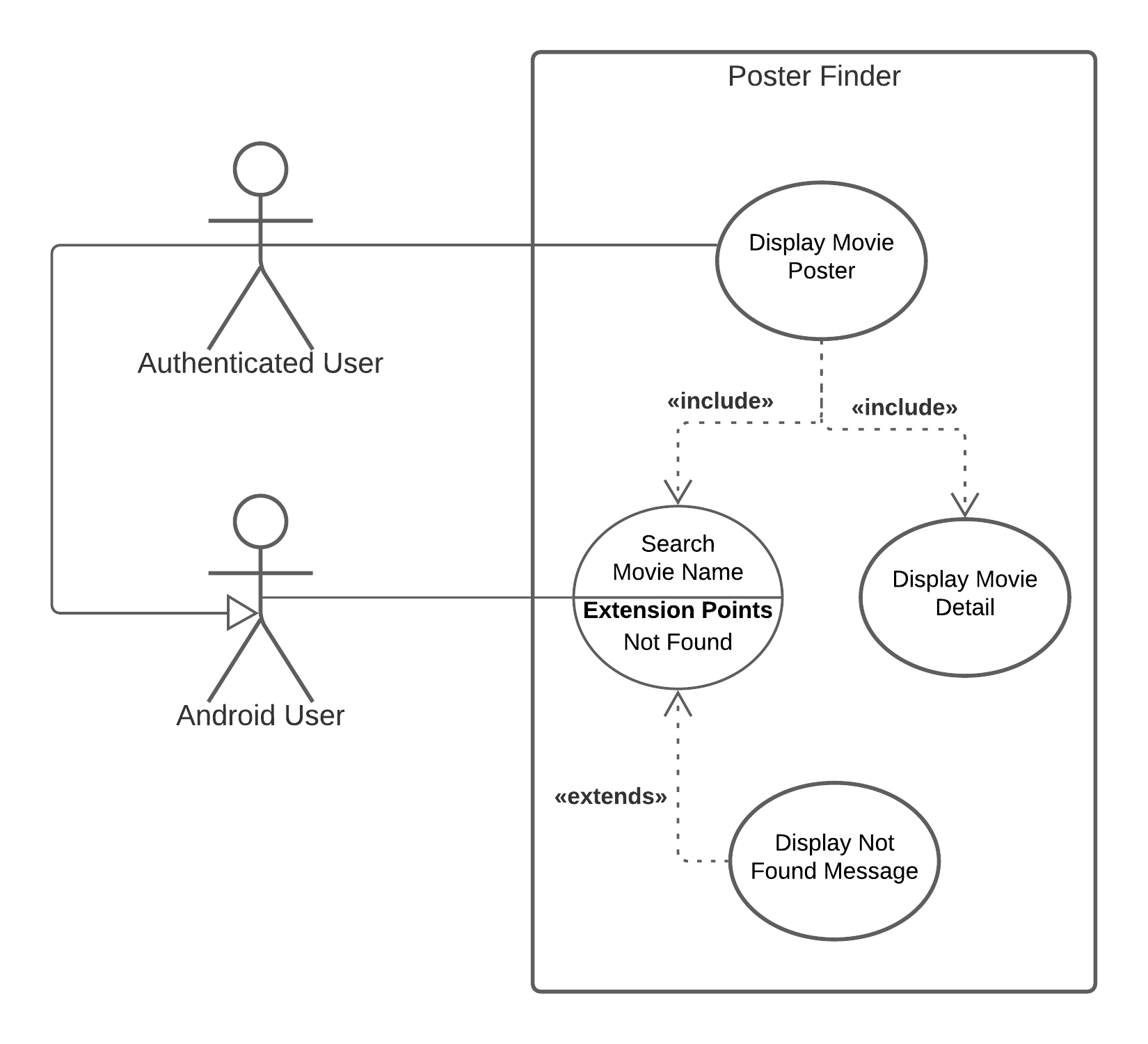
A good exercise is to try to understand what this diagram is telling you just by looking at it. It tells you some important aspects:
- This app can have two different types of actors: authenticated or not. Any Android user can search for a movie, but only an authenticated user can display the poster.
- The line ending with an empty triangle represents a fundamental relation you’ll see a lot in other diagrams. This is the way you represent the generalization. Here you’re saying that an authenticated user IS-A Android user. In this context, IS-A means “can do the same things that”. So an authenticated user can do, at least, all the things that an Android user can do.
- There are different types of use cases. Some represent the happy path, where everything goes well. However, alternative use cases describe what happens when something goes wrong. In the context of the Poster Finder app, a user might search for a movie, find it and display its poster. This is the happy path. On the other hand, it’s possible that the movie isn’t in the database, so the app has nothing to display. This isn’t necessarily an error, but it’s a use case that differs from the happy path and requires something different. In UML, you call the Not Found an extension point for the Search Movie Name use case. You represent it with an oval with a horizontal line in the middle.
- When you define the extension point, you also define the alternative use case. As you see in the diagram, you connect the alternative use case to the extension point using a dotted line with an open arrow with the «extends» stereotype. This means the Display Not Found Message use case extends the Search Movie Name use case for the Not Found extension point.
The extensive description above just proves that a picture — or in this case, diagram — is indeed worth a thousand words… or at least a couple hundred. :]
Creating a Deployment Diagram
The first question you want to answer is about the external system the app will talk to. This is the goal for the following deployment diagram.
Poster Finder Deployment Diagram

This is a very simple diagram that gives you lots of important information:
- The box symbol represents a node, which is any physical device. It could be a server machine or an Android device, like in this case.
- You use the same box symbol to represent the server. The box is empty because you don’t know how the server is implemented — and you don’t even care! :]
- What really matters is the interface the server exposes. You represent this with an open semicircle connected to the box that provides it.
- The semicircle representing the interface the server exposes has a label that describes what protocol — or in general, what interface — you need to access it. The Open Movie Database server exposes an API that uses JSON over HTTP.
- The lollipop matching the open semicircle represents a client for server’s interface.
- The client accessing the server using the HTTP protocol is the Poster Finder app, which you represent with the symbol of a component. A component is some software that lives in a container that, in this case, is the Android environment.
- An important property of UML is its extensibility. In this case, you’re adding some extra information the client needs to access a server when using the insecure HTTP protocol. You’re then using a note to describe the XML document your app needs to whitelist the server.
- The dotted line with the open arrow represents a dependency relation and it’s how you bind a note to its target.
It’s surprising how much information you can convey with a simple deployment diagram!
Creating a Dependency Diagram
The dependency relation is one of the most important things you can represent in a UML diagram. As you already learned with the deployment diagram, you represent dependency using an open arrow with a dotted line. This is also the relation you use when representing dependencies between packages.
Open the Poster Finder project with Android Studio, and you’ll get a structure like the following:
Poster Finder Code Structure
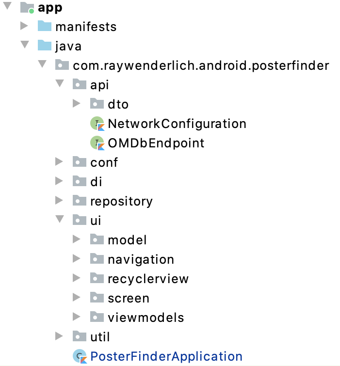
This tells you what the packages for the app are, but it doesn’t tell you their relation. This is what a package diagram, also known as a dependency diagram, can tell you.
Poster Finder Package Diagram

As you can see in this diagram, you:
- Represent each package with a file cabinet symbol with the name at the top.
- Describe subpackages, putting their symbols into the symbols of the superpackages. In this diagram, all the packages are direct or indirect subpackages of com.raywenderlich.android.posterfinder.
- Use the dotted line with an open arrow to represent dependencies between packages. In the previous diagram, for instance, recyclerview and viewmodels depend on the model subpackage.
- Can also use the dependency relation in case of multiple subpackages. In this diagram, for instance, you say that all the packages in ui depend on utils.
- See how the di package depends on the main abstraction of the app, like the ones in repository, ui or conf. This is because it’s where all the components are wired together.
As you learned earlier, each UML diagram should describe a single aspect of the system. This diagram describes dependencies between all the packages of the Poster Finder app. In theory, a package diagram allows you to tell more, like:
- Which components go into each package, with related visibility.
- Specific relations between packages like merge and include.
- Some of the main abstraction for each package with their relations.
Putting all this information in the same diagram would make it more complex to read and maintain. If you need to explain more, the advice is to create a new diagram. For instance, you could draw this diagram if you want to explain more about the main abstractions in the repository package.
Repository Package

With this diagram, you’re saying that the repository package:
- Contains the MovieRepository interface.
- Also has the OMDbMovieRepository class that implements MovieRepository.
- Contains the OMDbPagingSource class used by OMDbMovieRepository.
Although this is a perfectly valid UML document, it doesn’t give much useful information.
The use case and package UML diagrams are very important, but your apps have code you’ll want to explain and document. What, then, are the main diagrams you can use?