UML for Android Engineers
Learn how to draw UML diagrams to document your Android applications. By Massimo Carli.
Representing Objects
In the previous class diagrams, you saw how to represent a class. For instance, if you open the OMDbResponse.kt file in the api.dto package, you’ll find the following code:
data class OMDbResponse(
  @SerializedName("totalResults") val total: Int = 0,
  @SerializedName("Search") val items: List<MovieDto> = emptyList(),
  @SerializedName("Response") val response: String = ""
)
Using what you’ve already learned, you represent OMDbResponse with the following class diagram:
OMDbResponse

As you see, you replaced each {readonly} with a note that gives the same information without a lot of repetition. In the case of objects, you want to give different information, like:
- What are the objects’ types?
- If you have multiple instances of the same type, how do you distinguish one from the other?
- If it’s important, what are the values of some of the properties for that specific object?
All the objects are part of an objects diagram that is basically a snapshot of the memory of your system in a specific moment. This isn’t a diagram you use very often. In the case of the OMDbResponse, you might have something like the following:
ObjectDiagram – OMDbResponse
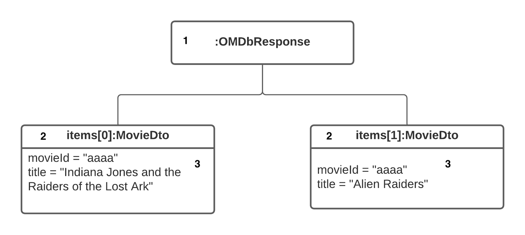
This is the object diagram of an instance of OMDbResponse containing two instances of MovieDto. In terms of the UML notation, you see that:
- If you have only one instance of a class and you don’t care what instance it is, you represent it with a rectangle with the name of the class with a : as the prefix. Basically, you use the notation :class-name.
- To distinguish different instances of the same class, use the notation instance-name:class-name. In this case, the two instances are part of the same list, so you can use the subscript notation. Again, as the name for the instances, you can use what you prefer, depending on what you want to describe.
- Sometimes it’s also useful to list the values for the instance properties of interest. In this example you list the values for
movieIdandtitle.
Object diagrams allow you to put on paper a snapshot of the memory of the system you want to describe. Objects are also important to describe how different instances collaborate with each other.
Understanding Collaboration Diagrams
A collaboration diagram is a way to describe how different objects interact with each other, with an emphasis on the objects themselves. Consider the following diagram that describes the main operations in the initialization of what you see in the MovieListFragment.kt file in the ui.screen package:
Example of Interaction Diagram

This diagram is very simple and it describes part of the initialization for MovieListFragment using some symbols:
- An interaction diagram describes objects you represent with a box containing the name of the instance and the name of the class following the instance-name:class-name conventions. In this case, note how the name is underlined.
- Like for
movieAdapter, you can explicitly state the name of the instance. In other cases, you omit it because you only have one or it’s simply obvious. - The diagram describes how the objects collaborate, drawing a line with a label that follows the conventions order:method-name. The order tells you when a method is invoked before or after another. The method name tells you what method an object invokes on another.
- In this diagram, note how
MovieListFragmentinvokes the static methodinflate()onFragmentMovieListBindingthat is a class. If this is important, a note makes this detail more explicit.
As said, an interaction diagram gives information about which objects interact and how. If you’re interested in the time sequence of the operations, a sequence diagram is probably the best choice.
Understanding Sequence Diagrams
If you want to describe in more detail how different objects interact with each other, the sequence diagram is the right tool for you. In the following diagram, you describe the same initialization process for the RecyclerView in MovieListFragment.
SequenceDiagram MovieListFragment

Notice a few interesting things:
- You represent each object with a box containing the name in the format instance-name:class-name. Again, if the name of the instance isn’t important, you can simply use the notation :class-name. Compare this with the collaboration diagram, and you can see how the name is now underlined.
- In a sequence diagram, time is important and it has a special symbol. You represent the lifetime of an object with a vertical dotted line starting from the object itself. In this diagram, the lifetime is vertical, but you could also give the same information with a horizontal line and a diagram that’s basically rotated 90 degrees.
- The vertical position of each object is also important. In this diagram, the
:MovieViewModelinstance is below the:MovieListFragmentone because it is created later. The same is true for the other instances. - Objects interact, invoking methods or, in a more formal way, sending messages. You represent this using horizontal lines ending in closed arrows with a label for the method name.
- The vertical rectangles on top of some portions of the timeline are activations. They allow you to group the method invocations that are part of the same method. The one for
onCreateView()is a good example and allows you to group the invocations toFragmentMovieListBindingandRecyclerView.
In the previous sequence diagram, you only represent method invocations and consider implicitly how to return the result. This is what happens most of the time, but what about asynchronous invocation?
Understanding Asynchronous Invocations
If your app is using some sort of asynchronous APIs like LiveData or, more generally, coroutines, how can you represent your code in a sequence diagram? Open the MovieListFragment.kt file in the ui.screen package and look at the following method:
  private fun search(query: String) {
    searchJob?.cancel()
    searchJob = lifecycleScope.launch {
      viewModel.searchMovie(query).collectLatest {
        movieAdapter.submitData(it)
      }
    }
  }
How would you represent it in a sequence diagram? Consider the following diagram that represents a simplified version of the method without the cancellation:
Sequence Diagram with Async messages

This is a very interesting diagram because there are some symbols for representing asynchronous messages, but there isn’t a unique way to represent them for Android. However, this sequence diagram has many interesting things to note.
- You have four different instances at the higher level of the diagram: :MovieListFragment, lifecycleScope:LifecycleCoroutineScope, :MovieViewModel and :MovieAdapter. This tells you that, in the context of the description of what happens in
search(), they already exist. - This diagram describes what happens when some client invoked
search(). This triggers thelaunch()message onlifecycleScope. It’s important to note here that thelaunch()message is synchronous and you use a closed arrow at the end of the horizontal line. - The previous note isn’t true for the
searchMovie()message on:MovieViewModel. This happens in the scope of the coroutine and you can represent it as an asynchronous message using a horizontal line ending in an open arrow. -
searchMovie()creates and returns aFlow<PagingData<UiMovie>>. In this diagram, you make the return type explicit using a horizontal dotted line, from right to left, ending in an open arrow. This is how you represent return values in a sequence diagram. - In this diagram, you also see an activation symbol close to another. When you send the
launch()message, you’re also passing a lambda that you can represent using the second activation symbol. - The last thing to note is the cross symbol that represents the end of the life of a particular instance. In this case, you represent the end of
Flow<PagingData<UiMovie>>.
This diagram is also an example of how important it is to focus on a single detail of the code you want to describe. This way, you can avoid the creation of overly complex and large diagrams.