Arduino Tutorial: Integrating Bluetooth LE and iOS
Learn how to control a servo wirelessly from your iPhone in this tutorial with Arduino, Bluetooth LE (low energy) and iOS. By Owen L Brown.
Illuminating an LED
The main objective of your Arduino program in this project is to receive the one-byte messages coming from the BLE Shield and use the contents of the message to set the servo’s position. But before you get too involved into the servo code, it would be nice to test your current connections.
The easiest way to do this is to write a small program that controls the built-in LED on the Uno. Think of it as the “hello world” equivalent on the Arduino. :]
Replace the code in your project with the following:
// Arduino Bluetooth LE Servo Controlled by iOS

int LED = 13;     // Most Arduino boards have an onboard LED on pin 13

void setup()  // Called only once per startup
{
  pinMode(LED, OUTPUT);     // Set pin as an output
  digitalWrite(LED, HIGH);  // Turn on LED (ie set to HIGH voltage)
}

void loop() // Continuous loop
{
  delay(500);
  digitalWrite(LED, LOW);
  delay(500);
  digitalWrite(LED, HIGH);
}
Since most Arduino boards have an onboard LED on pin 13, you can use the illumination of the LED as confirmation that your Arduino program is executing properly. You set the LED variable to 13 to refer to that pin.
In setup(), you set the initial state of the board. pinMode(LED, OUTPUT) sets pin 13 as a digital output, which means that the voltage on this pin can be set to HIGH (+5v) or LOW (0v). digitalWrite() sets the pin’s voltage; in the code above you’ve set it to HIGH to illuminate the LED.
After setup() has finished, loop() will run continuously. delay() will wait a certain number of milliseconds which you’ll use to get the LED to blink. After a 500ms delay, you turn the LED off by writing the value LOW; after another delay, you turn the LED back on.
Click the Verify button again to compile the program and check for any syntax errors. If your program compiles without issue, you’ll see Done Compiling in the status bar of the Arduino IDE. If not, read the status bar message for an indication of where you’ve messed up, fix the error and click the Verify button to make sure you’ve squashed the bug for good.
Now it’s time to program the code to the Arduino board and test the LED.
Make sure your Arduino is connected to your computer with the USB cable then click the Upload button (the one with the right arrow icon) to program the Arduino board. Once the upload process has finished, the Done uploading message should appear in the status bar as shown below:

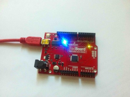
Check your Arduino board, and you should see the LED start to blink.
LED 13 is ON. Houston, we have communication.
If an error occurred, try the following things to diagnose your issue:
- Check that Arduino Uno is selected in the Tools/Board menu.
- Check that /dev/tty.usbserial… or /dev/tty.usbmodem… (or similar) is selected in the Tools/Serial Port menu.
- Check that you installed any required drivers for your Arduino board as noted earlier.
- Check that the BLE Shield is not assembled on the Arduino board during programming of the board.
If the LED works, you can be sure that the Arduino IDE is set up properly. You can now add some code to control the servo.
Interfacing With the Servo Control
A servo is a motor with a changeable rotational position. You control a servo by sending different frequencies of electric pulses to its control line.
Replace the blinking LED code in the current sketch with the following:
// Arduino Bluetooth LE Servo Controlled by iOS

#include <Servo.h>

int LED = 13;     // Most Arduino boards have an onboard LED on pin 13
Servo myservo;    // Create servo object to control the servo
The above code imports the Servo library and create a variable as an instance of the Servo class. By including the Servo library, you can create Servo objects which can be easily configured to control the servo hardware.
Next, add the following function:
void setup()  // Called only once per startup
{
  pinMode(LED, OUTPUT);     // Set pin as an output
  digitalWrite(LED, HIGH);  // Turn on LED (ie set to HIGH voltage)

  myservo.attach(9);        // Attach the servo object to pin 9
  myservo.write(0);         // Initialize servo position to 0
}
myServo.attach(9) indicates that output pin 9 of the Arduino Uno board will be connected to the servo, while write(0) sets the position of the servo to zero degrees.
That takes care of the servo initialization, but you’ll still need some code to handle the BLE communication. Before you tackle that, you should read through the following section on the fundamentals of serial communication.
Serial Communication
Serial communication is much like using a telephone. The speaker held to your ear is the receiver (RX) and the microphone is the transmitter (TX). Your transmitter is connected to the receiver of the person with whom you are talking, and your receiver is connected to their transmitter. This allows for bi-directional communication where either person can send or receive information.
By default, the Arduino uses pin 0 and pin 1 for serial communication. To communicate with the BLE Shield, this needs to be changed to pin 4 (RX) and pin 5 (TX). This guards against any data collision when the PC is uploading to the Arduino.
Add the following include to the top of the file:
#include <SoftwareSerial.h>
This will allow you to use the serial communication library.
Add the following variable underneath the LED and myservo variable declarations:
SoftwareSerial BLE_Shield(4,5);
This will create an instance of SoftwareSerial named BLE_Shield. The two parameters are pin numbers, so the BLE shield will use RX and TX lines 4 and 5 respectively.
Add the following line to the end of the setup() function:
BLE_Shield.begin(9600); // Setup the serial port at 9600 bps. This is the BLE Shield default baud rate.
This sets the serial communication, or baud rate, which is the speed at which data bits are transmitted. In order for two devices to communicate, they must use the same baud rate. Since the BLE Shield’s default baud rate is 9600, you set the Arduino serial port to match.
Finally, add the following function to the bottom of the sketch:
void loop()  // Continuous loop
{
  // See if new position data is available
  if (BLE_Shield.available()) {
    myservo.write(BLE_Shield.read());  // Write position to servo
  }
}
Eventually, your iOS device will be feeding data to the BLE shield. loop() has one job now: look for new bytes from the BLE shield’s RX line and pass them to the servo.
First, it calls BLE_Shield.available() to see if any bytes are available. If so, read the available bytes and write them to myServo. If there is no new data from the BLE Shield, then it loops around and checks again…and again…and again.
Save your Arduino project then click the Upload button to upload your new program to the Arduino board. The Done uploading message should appear at the bottom of the IDE. You’ll see the LED light up and stay lit, letting you know main() finished.
At this point, your Arduino code is complete and ready for communication with your iOS app via the BLE Shield.
The next logical step is to get familiar with how the BLE Shield functions; you’ll cover this in the next section.