iOS Assembly Tutorial: Understanding ARM
Learn how to read assembly in iOS – a useful skill when debugging your code or diagnosing why a crash has occurred. By Matt Galloway.
Calling the Function
First you need to add an attribute to the addFunction routine to indicate to the compiler not to perform a certain optimization. You’ve already seen how the compiler can optimize the code to remove unneeded instructions, but it can even remove function calls entirely and put the function code directly inline.
For example, the compiler might put the appropriate add instructions rather than call addFunction itself. In fact, compilers are so sophisticated these days that for a function like addFunction, it could perform the addition itself and never insert an add instruction at all!
For this tutorial, you don’t want the compiler to optimize and “inline” the function. Go back to the main.m file in the project and make addFunction look like this:
__attribute__((noinline))
int addFunction(int a, int b) {
    int c = a + b;
    return c;
}
Now add another function below it that looks like this:
void fooFunction() {
    int add = addFunction(12, 34);
    printf("add = %i", add);
}
fooFunction simply computes 12 + 34 by calling addFunction and then prints the result. I’ve used the C function printf rather than NSLog again to avoid Objective-C, which complicates things a little.
Select Product\Generate Output\Assembly File once again and make sure Archiving is the output setting. Then search for _fooFunction, at which point you should see something like the following:
_fooFunction:
@ 1:
	push	{r7, lr}
@ 2:
	movs	r0, #12
	movs	r1, #34
@ 3:
	mov	r7, sp
@ 4:
	bl	_addFunction
@ 5:
	mov	r1, r0
@ 6:
	movw	r0, :lower16:(L_.str-(LPC1_0+4))
	movt	r0, :upper16:(L_.str-(LPC1_0+4))
LPC1_0:
	add	r0, pc
@ 7:
	blx	_printf
@ 8:
	pop	{r7, pc}
This introduces some new instructions that this tutorial hasn’t covered yet, but don’t worry, they’re not complicated. Here goes:
In the two lines in the above assembly, r0 and r1 are loaded with the constants as defined in the function. Notice that they are being loaded into r0 and r1 such that they are in the right place for calling addFunction.
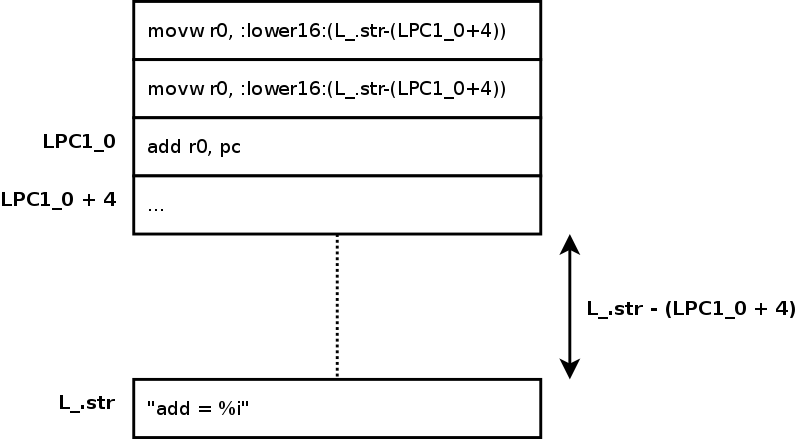
The string is initially found in the data segment of the object file created from main.m. If you search in the assembly for L_.str, you’ll find it. The first two instructions in this trio load the address of this constant, minus the address of the local label, LPC1_0 plus 4.
The reason for doing this little dance becomes apparent with the third instruction. This adds the program counter to that value. So r0 now holds the address of the string but will work no matter where L_.str ends up in the final binary.
The diagram below illustrates the memory layout. The difference L_.str - (LPC1_0 + 4) is free to change without the code loading r0 changing.

This is slightly beyond the scope of this tutorial, but modern ARM processors have two modes: ARM and Thumb. Thumb instructions are 16-bits wide whereas ARM instructions are 32-bits wide. There are fewer Thumb instructions, but using them often means smaller code size and better CPU caching.
You can usually get the benefit of smaller code size with the limited Thumb instruction set. You can read more about Thumb on Wikipedia.
Well, remember that lr contains the address of the next instruction to execute when returning from a function. So if you pop that value into the program counter, execution will continue from the place from which this function was called. This is often how return from a function is achieved, instead of a branch as seen in the assembly for addFunction.
- This instruction does a similar thing to the
add sp, #12that you saw previously. This time,r7andlrare “pushed” onto the stack, meaning that the stack pointer is decremented by 8, since bothr7andlrare 4 bytes. Note that the stack pointer is decremented and the two values are stored with the one instruction!r7is stored because it will be overwritten by this function and needs to be restored later;lris stored for a reason that will become apparent at the end of the function. - These two instructions are part of the move (
mov) family. Sometimes you’ll seemovs, sometimesmov.w, sometimes other things, but they all load a register with a value. You can “mov” data from one register to another, somov r0, r1will loadr0with the contents ofr1, leavingr1unchanged. - The stack pointer should be saved across function call boundaries, so
r7, one of the registers available for local variables, is used. You’ll note that the rest of the function doesn’t ever use the stack pointer orr7again, so this is slightly redundant. Sometimes even with optimizations turned on there are inefficiencies! - This instruction,
bl, performs the function call. Remember that the parameters to the function have been put in the relevant registers,r0andr1. Now this instruction performs what is known as a branch. Since this is abland not simply ab, a “branch with link” is performed, which means that before the branch, the link register,lr, is set to the next instruction in the current function. Recall that when returning from a function,lris used to know where to go. - This is the point to which the branch to
addFunctionreturns, after it does the hard work of adding the two numbers. Remember that return values of functions are stored inr0. This value is required as the second parameter of theprintfcall, so amovis used to bring this tor1. - The first parameter to the
printfcall is a string. These three instructions load a pointer to the start of the required string intor0. The string is stored in what is known as the “data segment” of the binary. But exactly where it will be is not known until the final binary is linked. - This instruction performs the call to
printf. This is slightly different than the otherblinstruction, in that it isblx. The x here stands for “exchange”, meaning that if required, the processor will switch modes. - This final instruction pops back off the stack the values that were pushed on in the first instruction. The registers in the list this time are filled with the values from the stack and then the stack pointer is incremented. Recall that
r7andlrwere pushed onto the stack, so why are those saved values restored and popped back tor7andpcrather thanr7andlr?
That is a very brief overview of some ARM instructions. There are many more instructions, but the ones shown here are the most important to understand initially. Here’s a quick recap of what they do, along with pseudo-code or a description:
-
mov r0, r1=>r0 = r1 -
mov r0, #10=>r0 = 10 -
ldr r0, [sp]=>r0 = *sp -
str r0, [sp]=>*sp = r0 -
add r0, r1, r2=>r0 = r1 + r2 -
add r0, r1=>r0 = r0 + r1 -
push {r0, r1, r2}=> Pushr0,r1andr2onto the stack. -
pop {r0, r1, r2}=> Pop three values off the stack, putting them intor0,r1andr2. -
b _label=>pc = _label -
bl _label=>lr = pc + 4; pc = _label
Wahoo! Now you can read some ARM assembly!
