Arduino Tutorial: Creating Pong
An Arduino tutorial about making a pong game with an LCD and some push buttons. By Felipe Laso-Marsetti.
Adding the potentiometer
Doing good so far :] just a few more connections and you’ll be ready to test your LCD.

Time to step back for a minute as you’re about to connect a potentiometer (commonly referred to as ‘pot’) to control the LCD’s contrast. You’ll be needing a 10k potentiometer. Potentiometers can come in many different shapes so don’t worry if yours looks different. What’s important is the value since, depending on the resistance, you don’t want to send too much or too little voltage to the LCD’s contrast pin.
As a challenge, try to find what each pin on the potentiometer does and what they correspond to.
[spoiler title=”Solution”]From left to right, the pins correspond to ground, input and output which you can get from the potentiometer documentation .[/spoiler]
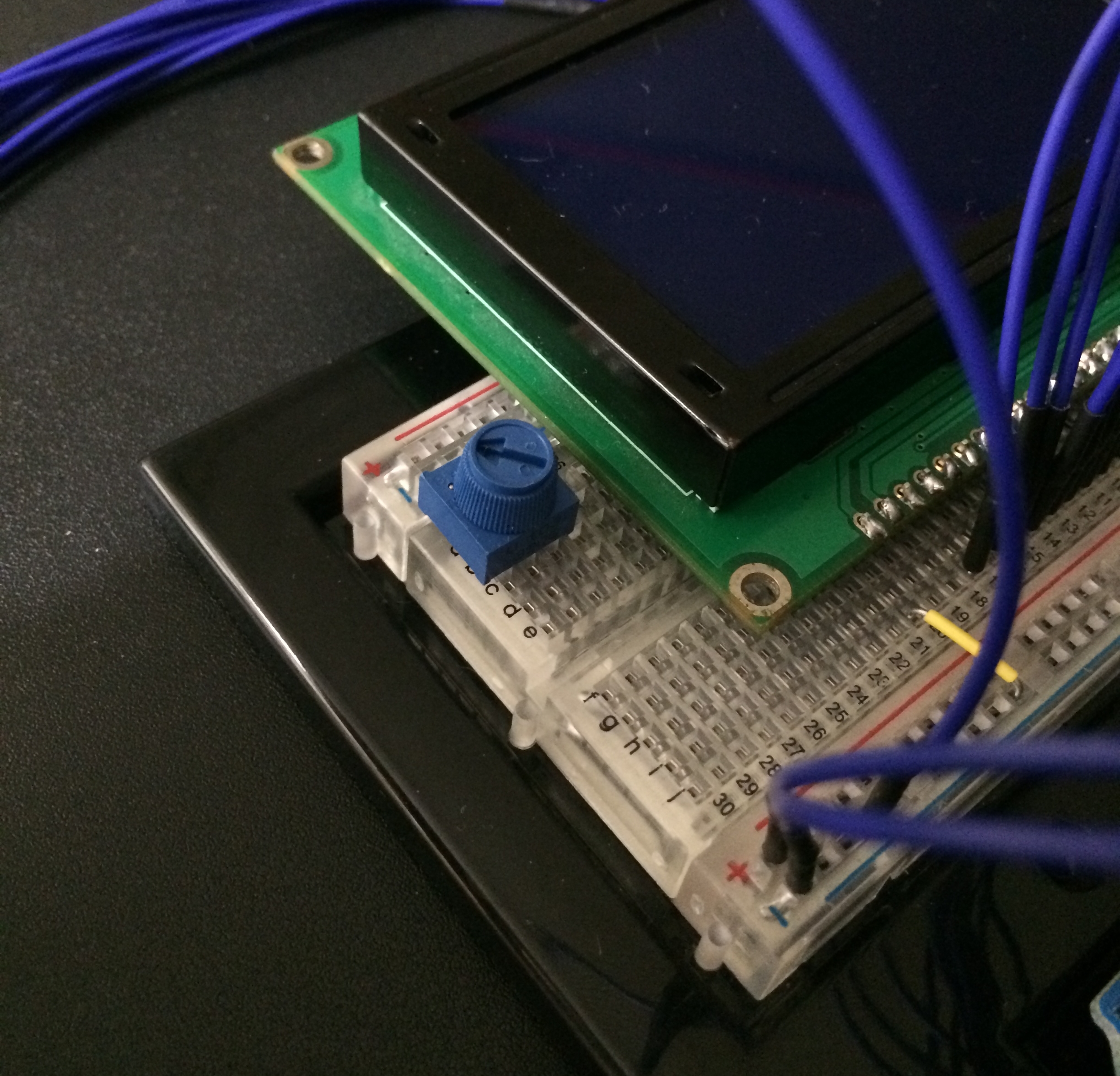
Here’s what the potentiometer looks like:

The yellow arrow indicates the corner with a ridge and circle on the potentiometer to show you what each pin does. As you can see there’s a pin you connect to ground, one for voltage input and one for the output voltage. If you have a different potentiometer, or want to learn more about them, you can find a cool guide on connecting potentiometers here.
Testing the potentiometer (Optional)
If you have a multimeter, it’s always good practice to test out your components by comparing their real world values to the values you expect. If you don’t have one, feel free to skip ahead to the section Connecting the potentiometer.
To measure the resistance of your potentiometer and to ensure that it’s 10k Ohms, take out your multimeter and set it to measure resistance. Make sure you set it to a value larger than 10k so you get an accurate reading. This is how you connect both legs of the multimeter to the potentiometer:

You connect the negative and positive pins of the multimeter to the in and out pins of the potentiometer, respectively. The Yellow arrow is there to indicate the order of the legs, as previously shown.
Turn the pot all the way down and get a measurement, then all the way up and get that measurement:

The left side shows the value with the pot turned all the way down, and the right side shows the value with the pot turned all the way up. Notice how the multimeter is set to measure up to 20K Ohms, which means that the 10.12 value means 10.12K Ohms (approximately).
Resistors and potentiometers have a percentage by which their resistance can vary. You can usually buy more expensive hardware to reduce the variation, if you so desire, but for this scenario a small change like 120 ohms will not affect your circuit.
Connecting the potentiometer
Having learned about potentiometers, how to measure their resistance value, and what each pin does, it’s time to put your 10K pot to use in the circuit. Go ahead and connect the potentiometer to the breadboard next to your LCD:
Connect a jumper wire from the negative rail of the breadboard (ground) to the ground pin of the pot:
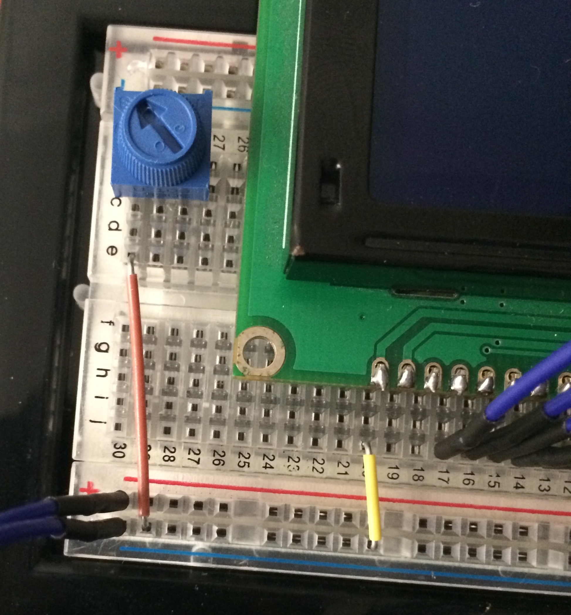
Now connect a jumper wire from the input pin of the pot to the Contrast in row of the LCD, and one from the output pin of the pot to the Contrast out row:
This will let you control the contrast of your LCD’s display by simply turning the knob in the potentiometer. Pretty cool, huh?
Finishing the LCD’s connections
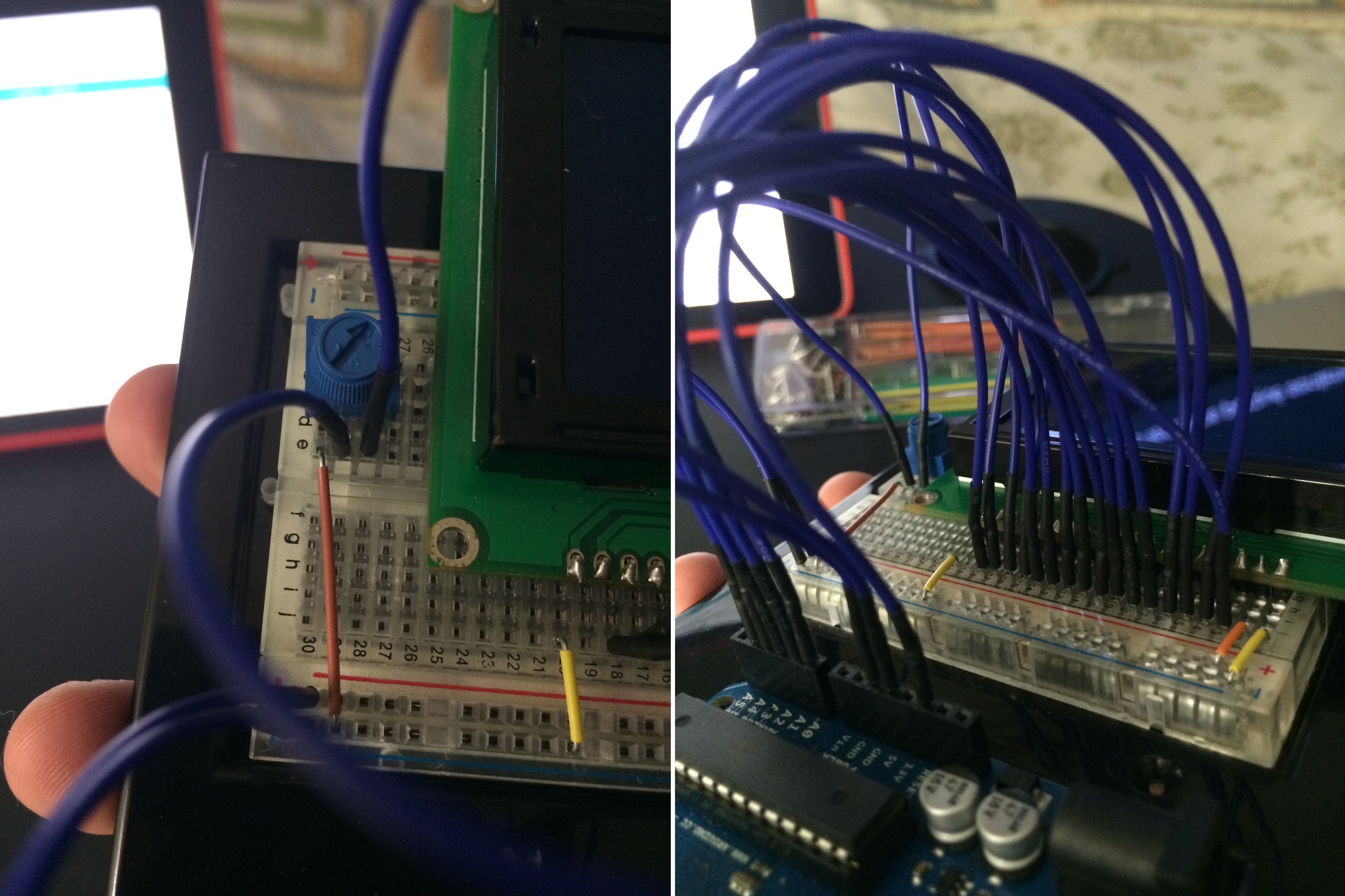
Finally, and to complete the connections to the LCD, connect a jumper wire from the 3.3V output on the Arduino Uno to the Backlight +5 row of the LCD.

Why are you connecting the LCD’s sidelight voltage input to 3.3 volts when the electrical characteristics previously stated that the typical voltage is 4.2V?
Well, the maximum voltage is 4.6V and even after all the connections you’ve made the LCD will probably be receiving close to 5V. A jump from 4.6V to 5V may not seem like much but it could damage your LCD in the long run. It’s always very important to pay attention to the data sheet and the maximum voltage, current, and power that a component can support.
If you didn’t do this, you would need to get a resistor to lower the voltage to 4.6V or lower, and you may not have one handy. By sending 3.3V to the LCD’s sidelight panel you not only avoid damaging your LCD, but you also avoid having to use a resistor. And the end result works well, your LCD has more than enough voltage to shine very bright should you want to play without any lights turned on :].
Testing the LCD connection to Arduino
Hurray! You’ve successfully connected the LCD to your Arduino board. It was quite a lengthy process but you have learned about the electrical characteristics of an electronic component, how potentiometers work, some nice tips about voltage and making sure your devices don’t get damaged, and more!
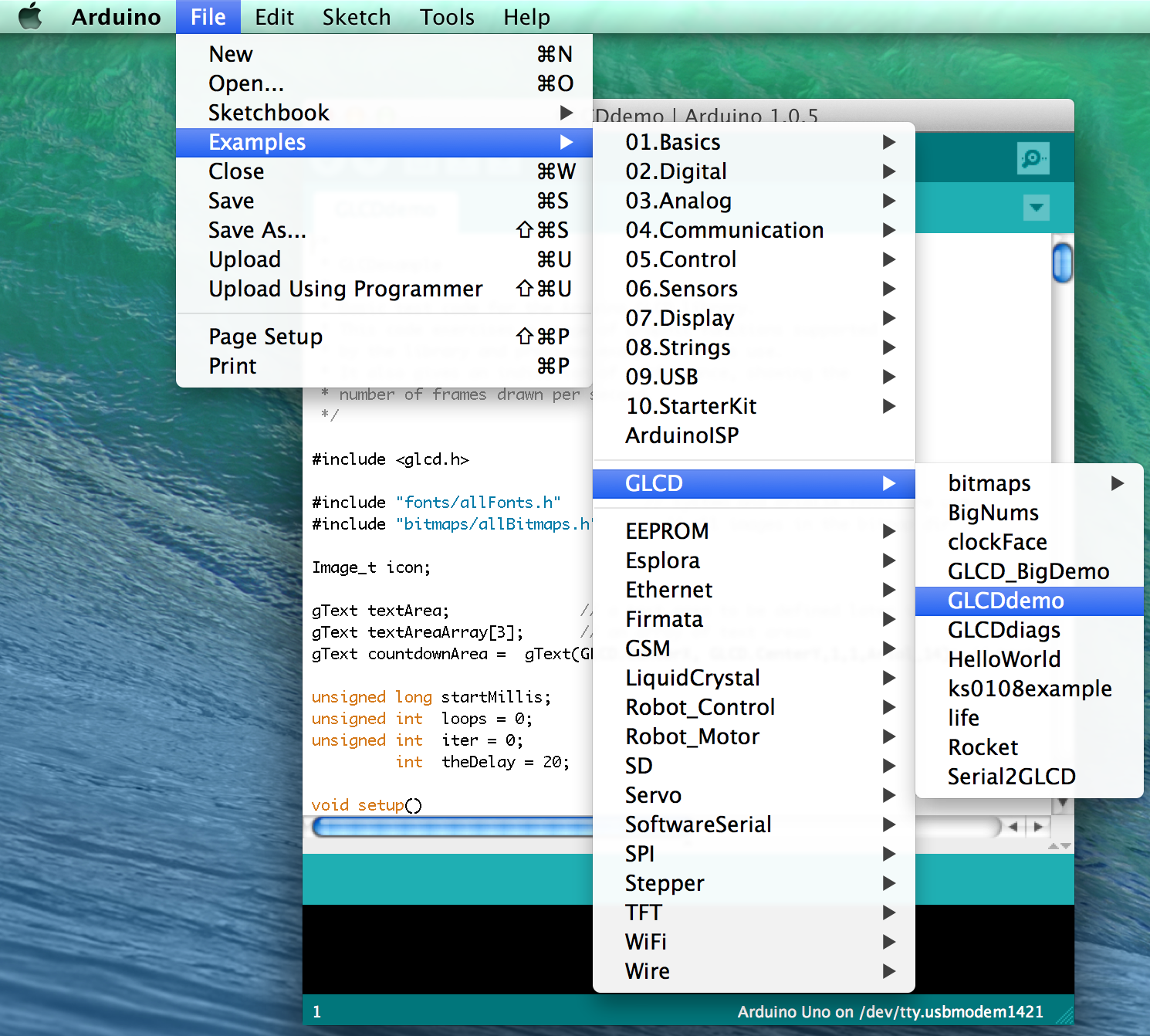
Having set everything up, it’s time to test your connection. Fortunately the GLCD library has some examples and templates that you can upload to your Arduino in order to test everything’s working correctly. Open the Arduino IDE and go to File\Examples\GLCD\GLCDdemo:
Now it’s time to upload the sketch. Connect the USB cable to your Arduino and to your computer. Make sure the correct model for your board is selected under Tools\Board and that the Serial port under Tools\Serial is using the USB port you connected your Arduino to. With that ready, go to File\Upload or hit Command+U.
Wait a few seconds for the sketch to upload and behold your awesome little console starting to take shape.

In OS X Mavericks (10.9), Apple seems to have changed the USB drivers and this may cause conflicts when uploading a sketch to Arduino. There’s a thread on the Arduino forums that proposes uninstalling and re-installing the previous drivers when running OS X Mavericks.
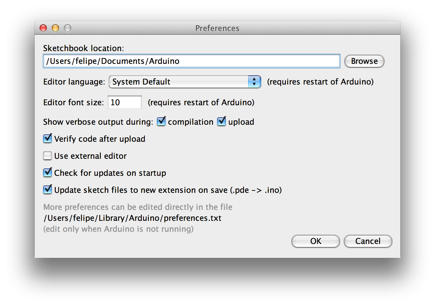
You may not like tampering with your default install of OS X or modifying any of its drivers or inner workings. If that’s the case, one solution which often works is to turn on verbose output during compilation and upload, by going to Arduino\Preferences, and hitting the Arduino Uno’s reset button right before the sketch begins to upload.
If you see a line with something like this: avrdude: stk500_recv(): programmer is not responding then uploading has failed, and what usually did the trick for me was unplugging the USB cable from the computer and attempting to upload using the “reset” trick again. It’s tedious, yes, but let’s hope Arduino has a solution for this soon.