Arduino Tutorial: Creating Pong
An Arduino tutorial about making a pong game with an LCD and some push buttons. By Felipe Laso-Marsetti.
Soldering the LCD
Soldering is not that difficult, and once you start it’s really quite addicting and fun :]
As mentioned previously though, it’s quite dangerous and a soldering iron can give you severe burns if you are not careful. Because soldering is not something that can be easily taught in pictures (specially trying to soldering something while taking a photo with a cell phone), here’s a cool YouTube video that will show you how to do it:
Soldering requires practice and is not something that can be mastered in just a couple of minutes or by watching a tutorial. Try practicing by soldering together some jumper wires, the inner wires of an ethernet cable, LEDs, resistors, or other simple items like header pins.
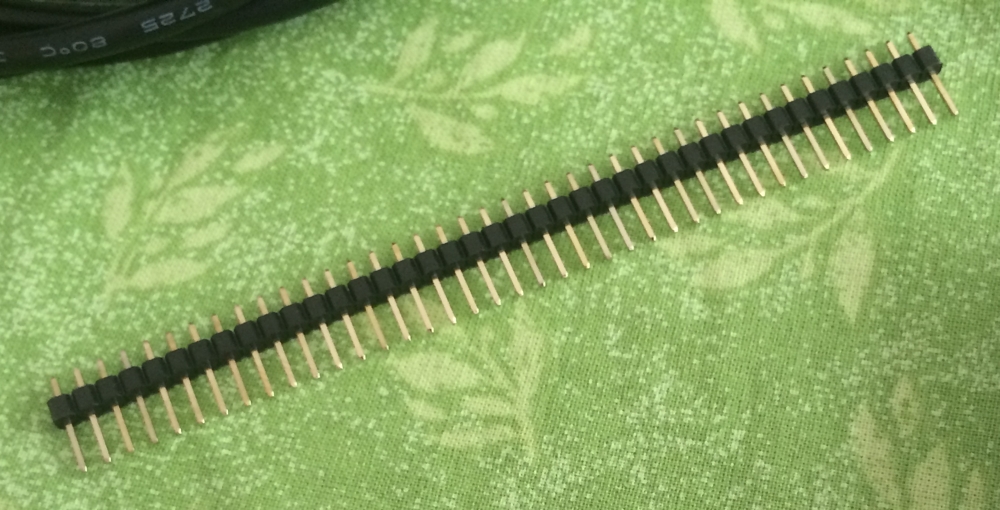
Once you are comfortable with using a soldering iron, break off 20 male-to-male header pins:
Take the smaller or thinner end of the header pins depending on the type you have and put them through the LCD’s holes from the bottom. Next, solder the header pins to the LCD:
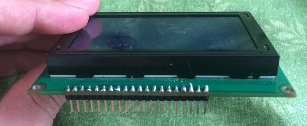
As you can see, these are not the solder joints of an expert :]. Once you’re done you will probably feel like this:

Don’t worry, practice makes perfect. The important things to do here are to be very careful avoiding getting burns or inhaling any of the fumes from the solder, and to make sure each pin is connected to the corresponding hole of the LCD and only to one hole. If not, you will have a short circuit in the LCD and things will not work correctly.
Connecting the LCD
Now that you have the LCD soldered to the header pins, it’s time to start connecting it to your Arduino board. Before getting started it’s a good idea to find the data sheet for your LCD’s model. In my case, and assuming you are using an LCD based on the 12864E model, you will find a document like the one found here.
Don’t worry if this document seems a bit daunting. You only have to understand what each pin corresponds to, how to connect it to the Arduino Uno, and some basic information like the electrical characteristics. How about you start with the latter:
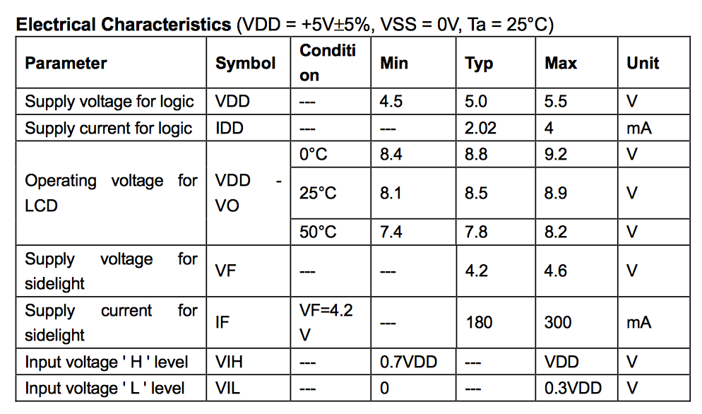
The table above shows the parameter for the LCD, its symbol, the unit it uses, and the minimum, average and maximum values for each particular parameter. It’s very good to pay attention to this as you don’t want to damage any of your equipment. If you were to supply the LCD with a value that exceeds the maximum for a given parameter you will likely permanently damage it.
For now, you don’t have to understand every single value shown here (or everything in the data sheet for that matter), but do take this into account for future projects that you build on your own. If there is something that you are not sure about you can always search for an answer online, or ask in the Arduino (or other) forums.
Now take a look at the LCD’s dimensions section:

This is shown as if looking at the LCD from the top. The right-most pin is pin number 1, and the left-most pin is pin number 20 for the 12864E model (reversed for example on the 12864H model). This is of importance when looking at the pin values and connecting them to the Arduino board. Here are the LCD’s interface pin connections for the 12864E:
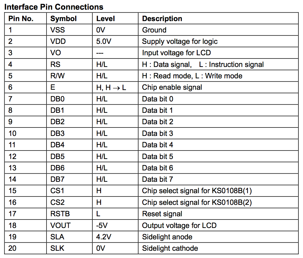
The LCD is divided into two, 64×64 sections, this is why there are pins for chip select (to draw on the left side of the screen or the right). There are also data pins to control the data that is drawn to the screen, pins for the LCD’s backlight, contrast, ground and voltage input, reset, and a couple others.
But where does each pin for the LCD go into the Arduino board? For that, you need to take a look at the GLCD documentation, available here. Scroll down a little bit in the document and you’ll see a table similar to the one below:

The table lists the pins for several different Arduino boards, in your case you want to use the left-most column titled Arduino Pins unless you’re using a board different than the Arduino Uno. Moving on you will notice a column with comments where appropriate and three columns for Panels A, B, and C.
These columns are what you need to focus on for now. Depending on your display type and what the data sheet says, your panel may need to be connected differently.
As a challenge, try and find what type of panel connection you need to use for an LCD based on the 12864E model.
[spoiler title=”Solution”]The panel type is B. You can see the highlighted row for panel type B. Compare your LCD’s data sheet with the panel types and try to find a connection that corresponds to your LCD. In the case of the J12864E LCD the chip select pins are number 15 and 16, which is what helped determine that panel type B is the connection you need to follow.[/spoiler]
Once you’ve determined what panel type you need to use for your connection, scroll down a bit further in the GLCD documentation and look at the graph showing how to connect the LCD panel to the Arduino board. Here’s the graph for panel type B:

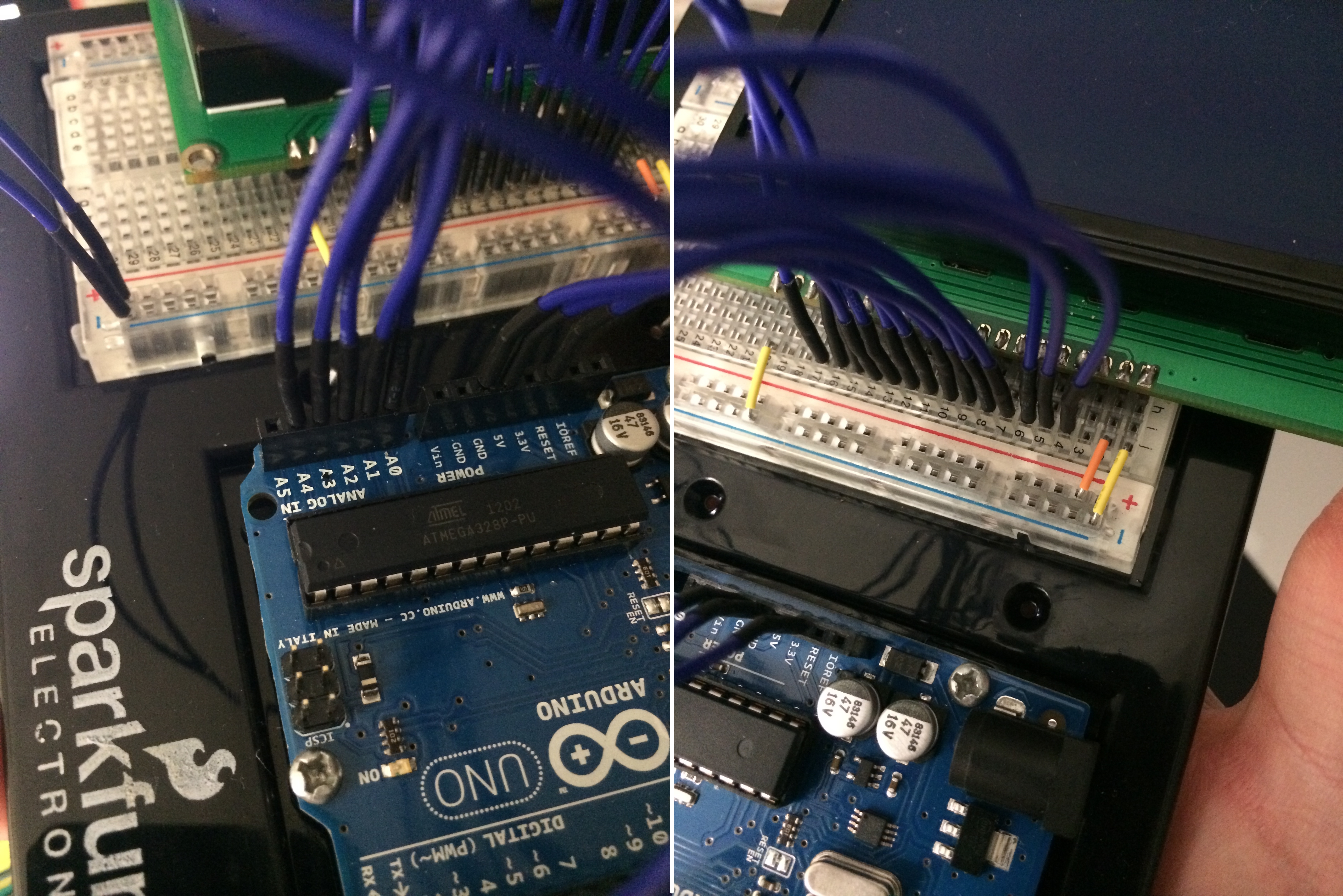
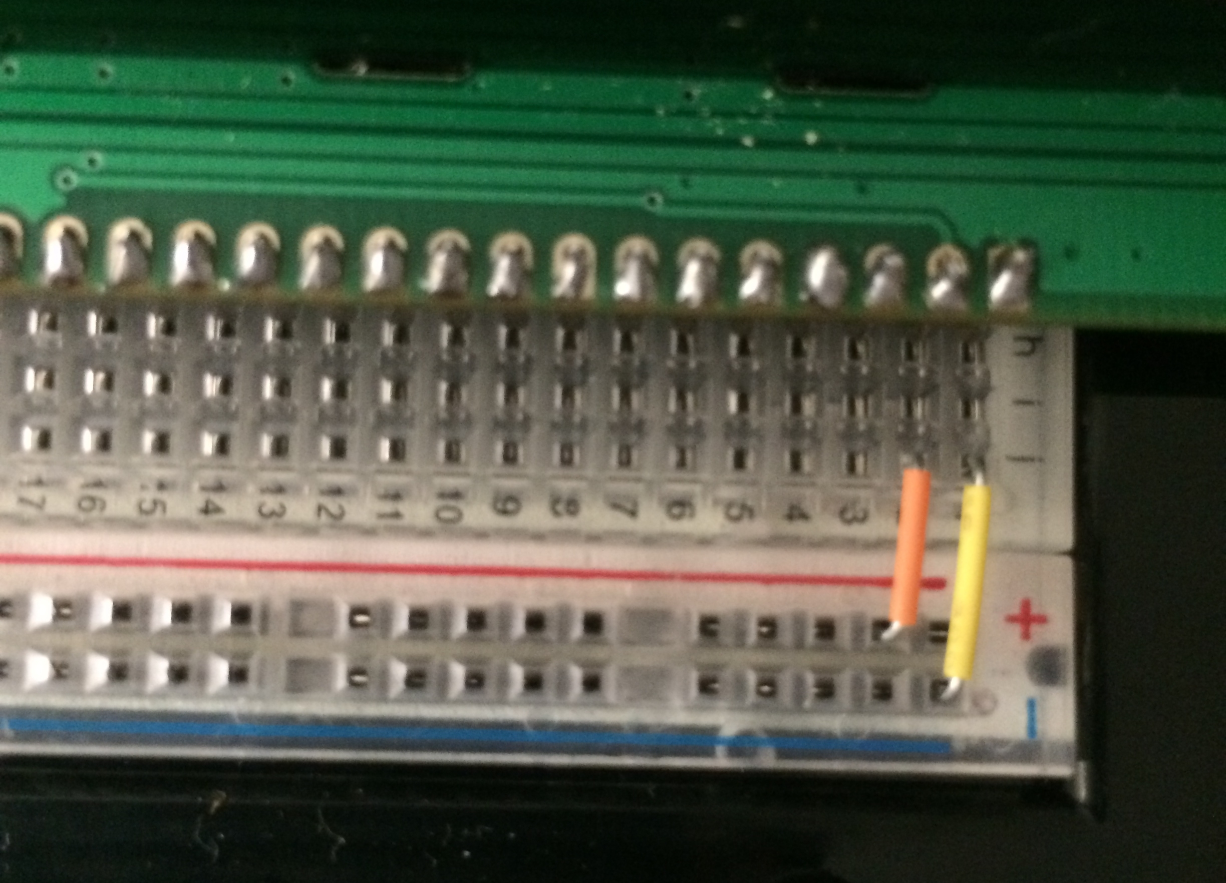
You’re now equipped with all the information you need to successfully connect the LCD. Grab a breadboard with at least 30 rows and connect the LCD as shown:

Notice how pin 1 in the LCD is connected to row 1 on the breadboard. This is not necessary but it will make it easier to know what pins you’re connecting the jumper wires to. Grab a pair of jumper wires and connect the positive rail on the breadboard (shown in red above) to the 5V output on the Arduino, and the negative rail (shown in blue above) to the Arduino’s ground.
For the rest of the connections, make sure to reference the GLCD panel chart from earlier to identify which pin on your LCD corresponds with the instruction listed below. LCD pins are referenced in bold and use the naming convention found in the Function column of the same chart:
On the other end of the breadboard’s positive and negative input rails, jump a couple of wires from the +5 volt row of your LCD to the +5V rail of the breadboard and from the Gnd row to the ground rail:
Connect the Reset row of the LCD to the Arduino’s Reset pin:

Connect the CSEL1 and CSEL2 rows to the A0 and A1 pins on the Arduino, respectively:
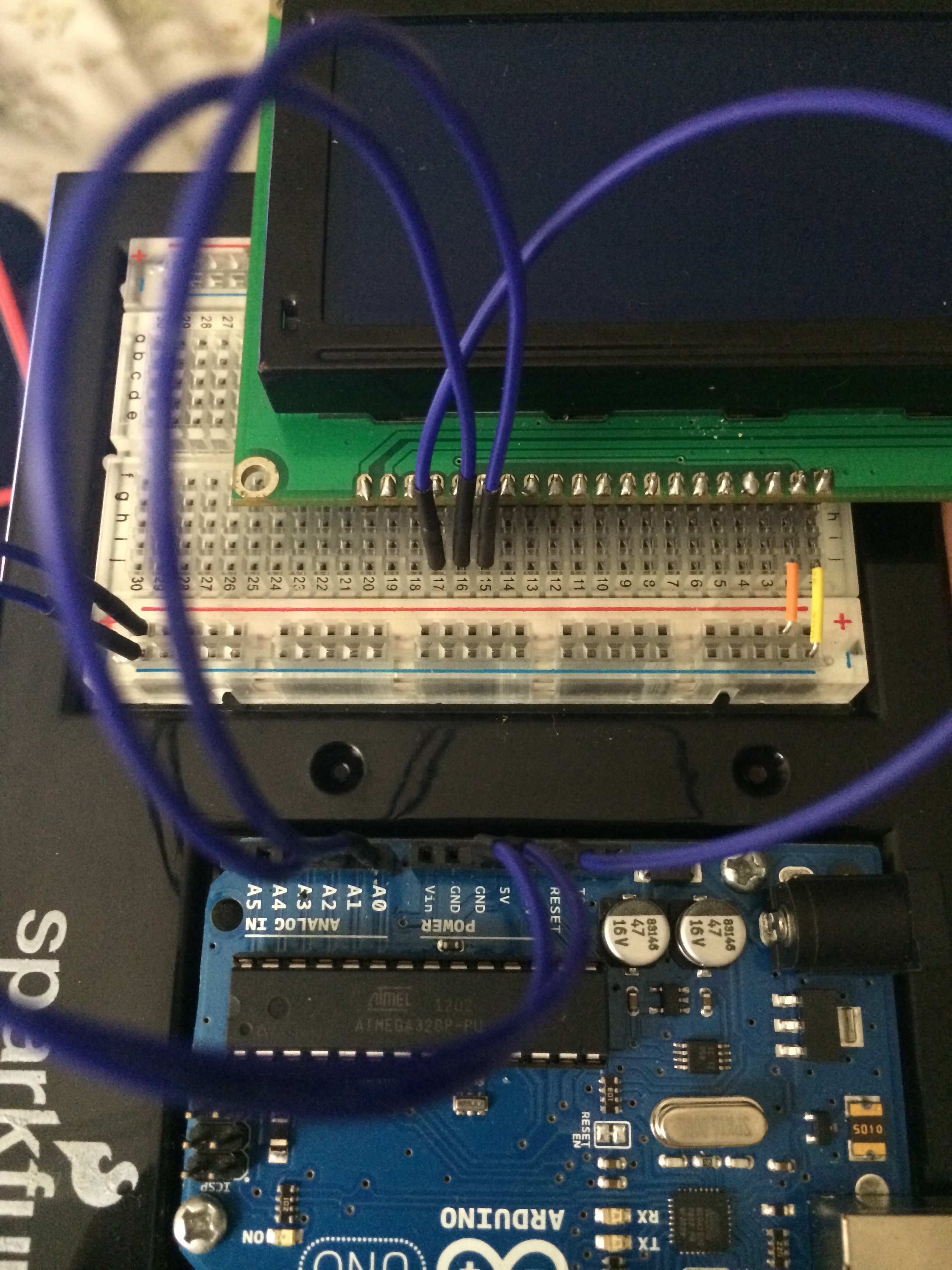
Now connect the Data lines (D0 – D7) as follows:
- D0 to pin 8
- D1 to pin 9
- D2 to pin 10
- D3 to pin 11
- D4 to pin 4
- D5 to pin 5
- D6 to pin 6
- D7 to pin 7

Connect a jumper wire from the Backlight Gnd row to the ground rail:

Now connect the R_W row to pin A2, D_I row to pin A3, and EN row to pin A4: