Volumetric Light Scattering as a Custom Renderer Feature in URP
Learn how to create your own custom rendering features with Unity’s Universal Render Pipeline by adding some volumetric light scattering to a small animated scene. By Ignacio del Barrio.
Drawing the Light Source
With the material created, you’ll now draw the actual light source.
Replace // TODO: 1 with the following lines:
context.ExecuteCommandBuffer(cmd);
cmd.Clear();
This prepares the command buffer so you can start adding commands to it.
The first graphic command you’ll issue will render the main light source. To keep it simple, you’ll draw the skybox, which contains the shape of the sun. This should yield very good results!
Add these lines below the previous code:
Camera camera = renderingData.cameraData.camera;
context.DrawSkybox(camera);
For ScriptableRenderContext to provide DrawSkybox, it needs a reference to the camera. You get this reference from RenderingData, a struct that provides information about the scene.
Referencing Unity Default Shaders
Next, you’ll draw the occluders, which are all the objects in the scene that can potentially block the light source. Instead of keeping track of these objects, you’ll use their shaders to reference them during rendering.
In this project, the objects all use Unity’s default shaders. To support default shaders, you have to fetch the shader tag ID for all the default shader passes. You’ll do this once and cache the results in a variable, using lists.
To use C# lists, you must add this line at the top of the file:
using System.Collections.Generic;
Next, declare the following field at the top of LightScatteringPass:
private readonly List<ShaderTagId> shaderTagIdList =
    new List<ShaderTagId>();
Then, add the following code in the constructor to populate the list:
shaderTagIdList.Add(new ShaderTagId("UniversalForward"));
shaderTagIdList.Add(new ShaderTagId("UniversalForwardOnly"));
shaderTagIdList.Add(new ShaderTagId("LightweightForward"));
shaderTagIdList.Add(new ShaderTagId("SRPDefaultUnlit"));
Drawing the Occluders
Once you have the default shader IDs, you can draw the objects that use those shaders.
Go back to DrawSkybox() function and add the following line below it:
// 1
DrawingSettings drawSettings = CreateDrawingSettings(shaderTagIdList,
    ref renderingData, SortingCriteria.CommonOpaque);
// 2
drawSettings.overrideMaterial = occludersMaterial;
Here’s what you’re doing with this code:
- Before you draw anything, you need to set up a few things.
DrawingSettingsdescribes how to sort the objects and which shader passes are allowed. You create this by callingCreateDrawingSettings(). You supply this method with the shader passes, a reference toRenderingDataand the sorting criteria for visible objects. - You use the material override to replace the objects’ materials with
occludersMaterial.
Next, add the following after the previous code:
context.DrawRenderers(renderingData.cullResults,
    ref drawSettings, ref filteringSettings);
DrawRenderers handles the actual draw call. It needs to know which objects are currently visible, which is what the culling results are for. Additionally, you must supply the drawing settings and filtering settings. You pass both structs by reference.
You’ve defined the drawing settings already, but not the filtering settings. Once again, you can declare them once, so add this line at the top of the class:
private FilteringSettings filteringSettings =
    new FilteringSettings(RenderQueueRange.opaque);
FilteringSettings indicates which render queue range is allowed: opaque, transparent or all. With this line, you set the range to filter any objects that aren’t part of the opaque render queue.
The last thing you’ll do is clean up the resources you allocated when executing this render pass. To do that, replace OnCameraCleanup() with:
public override void OnCameraCleanup(CommandBuffer cmd)
{
    cmd.ReleaseTemporaryRT(occluders.id);
}
Congratulations, you’ve made a lot of progress! Save the script, click Play and, guess what… everything’s still the same. Don’t worry, you’ll see why in the next section.
Inspecting With the Frame Debbuger
While you can’t see anything new in the scene, something different is happening under the hood. Next, you’ll use the Frame Debugger to inspect the renderer and see if the texture is being drawn properly.
Make sure you’re still in Play mode with the Game view selected. Select Window ▸ Analysis ▸ Frame Debugger, which will open a new window. Dock the window next to the Scene tab, press Enable and you’ll see this:
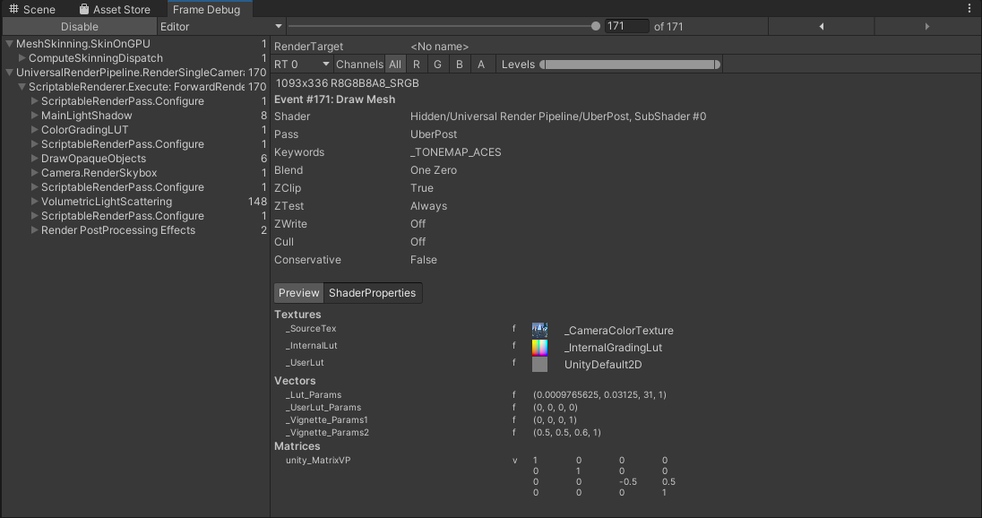
The main list shows the sequence of graphics commands in the form of a hierarchy that identifies where they originated.
Select VolumetricLightScattering and expand it. You’ll notice that the Game view changes. If rendering happens in a RenderTexture at the selected draw call, the contents of that RenderTexture display in the Game view. This is the occluders map!
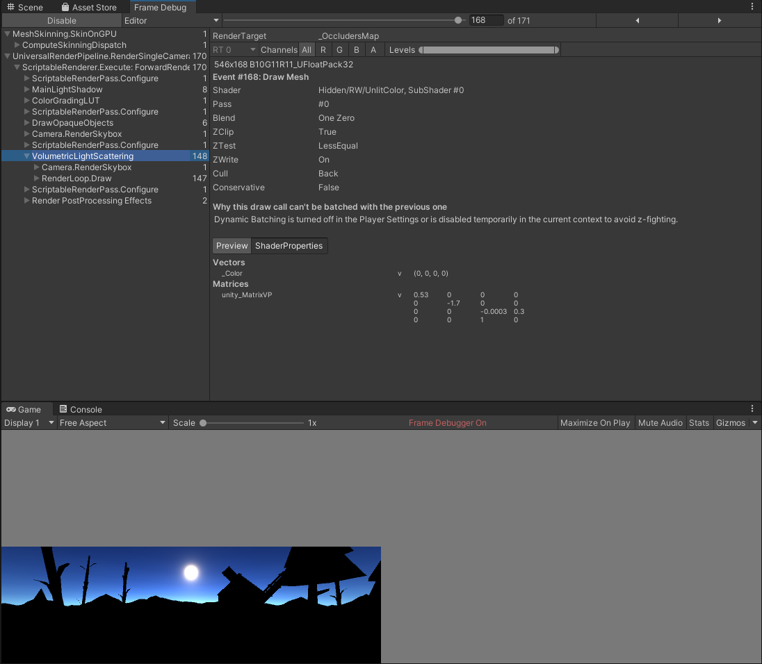
If you kept the default resolution scale settings, you’ll see the texture is half the screen size. You can select the individual draw calls to inspect what they do. You can even step through each draw call:

OK, the occluders map works. Click Disable to stop debugging.
Refining the Image in Post-Processing
Now to refine the image by blurring it in post-processing.
Implementing the Radial Blur Shader
Radial blur is achieved by creating a post-processing fragment shader.
Go to RW/Shaders, select Create ▸ Shader ▸ Image Effect Shader and name it RadialBlur.
Next, open RadialBlur.shader and replace the name declaration with:
Shader "Hidden/RW/RadialBlur"
This defines the new radial blur shader.
Next, you need to tell the shader about the settings you defined in the renderer feature. In the property block, add the following below _MainTex:
_BlurWidth("Blur Width", Range(0,1)) = 0.85
_Intensity("Intensity", Range(0,1)) = 1
_Center("Center", Vector) = (0.5,0.5,0,0)
_BlurWidth and _Intensity control how your light rays look. _Center is a Vector for the screen space coordinates of the sun, the origin point for the radial blur.
Combining the Images
For your next step, you’ll execute this shader on the occluders texture map and overlay the resulting color on top of the main camera color texture. You’ll use blend modes to determine how to combine the two images.
Start by going to SubShader and removing this code:
// No culling or depth
Cull Off ZWrite Off ZTest Always
Replace it with this:
Blend One One
This line configures the blend mode as additive. This adds both images’ values to the color channels and clamps them to the maximum value of 1.
Next, declare the following attributes above frag():
#define NUM_SAMPLES 100

float _BlurWidth;
float _Intensity;
float4 _Center;
The first line defines the number of samples to take to blur the image. A high number yields better results, but is also less performant. The other lines are the same variables you declared in the property block.
The actual magic happens inside the fragment shader. Replace frag() with this code:
fixed4 frag(v2f i) : SV_Target
{
    //1
    fixed4 color = fixed4(0.0f, 0.0f, 0.0f, 1.0f);

    //2
    float2 ray = i.uv - _Center.xy;

    //3
    for (int i = 0; i < NUM_SAMPLES; i++)
    {
        float scale = 1.0f - _BlurWidth * (float(i) /
            float(NUM_SAMPLES - 1));
        color.xyz += tex2D(_MainTex, (ray * scale) +
            _Center.xy).xyz / float(NUM_SAMPLES);
    }

    //4
    return color * _Intensity;
}
In the code above, you:
- Declare
colorwith a default value of black. - Calculate the ray that goes from the center point towards the current pixel UV coordinates.
- Sample the texture along the
rayand accumulate the fragment color. - Multiply
colorbyintensityand return the result.
Save the shader and go back to Unity. You’ll test the new shader by creating a new material and dragging the shader file onto it.
Start by selecting the material and assigning occludersMapExample.png in the texture slot. Find this texture in RW/Textures.
Now, you’ll see the shader effect on the preview window. Change the preview shape to a plane and play around with the values to get a better understanding of the shader attributes.

Fantastic, the effect is almost done.