Arduino Tutorial for Complete Beginners: Using a Button
This tutorial is for those who want to learn more about how electronics (like buttons) work. You’ll use an open-source micro-controller called the Arduino to make a LED light turn on and off. By .
Imagine your alarm goes off, and due to a late night you hit the snooze button and get right back to sleep. You realize you’re late for work so you punch a few buttons on your phone to call your boss to tell him a story about how you got a flat tire. You quickly start your car with the remote starter and set the alarm for the house.
I bet some of you have been in a scenario like that once or twice, but you probably weren’t thinking about an invention that you were using that changed the technology industry: the button!
A button is simply a device you can press to connect two pieces of metal together, allowing a current to pass. It’s extremely handy for all sorts of applications.
This tutorial is for those who want to learn more about how electronics (like buttons) work. You’ll use an open-source micro-controller called the Arduino to make a LED light turn on and off.
This tutorial is for complete beginners to Arduino development, but it also goes well with Dani Arnaout’s tutorial if you’ve already gone through that one.
OK, so keep scrolling that mouse button to get started!
What Do I Need?

The first thing you need to do is get a couple parts. You can get all of these parts at RadioShack, or you can order them online.
- An Arduino. This is the microcontroller you will be programming. In my case I am using an Arduino Uno.
- A LED. An LED stands for light-emitting diode – it’s basically a small light that you’ll be able to turn on and off with your button.
- A push button. The button should allow current to pass when you push it down and block electricity when you let it go. This is also called a momentary switch.
- A few wires.
- A breadboard and a resistor (optional). When working with electronics it’s quite handy to have a breadboard and some resistors, but this is optional – I’ll show you both ways.
Note from Ray: When testing out this tutorial, I ended up buying all of my components online from Sparkfun Electronics. I bought:
- A Sparkfun Inventor’s Kit. This contains almost everything you need for this tutorial and the others on this site, along with a fun instruction book with other fun projects you can try.
- A Momentary Push Button Switch – 12mm Square. I think the starter kit might actually come with a button already so you might not need this, but I couldn’t find mine so I ordered one separately.
About the Arduino
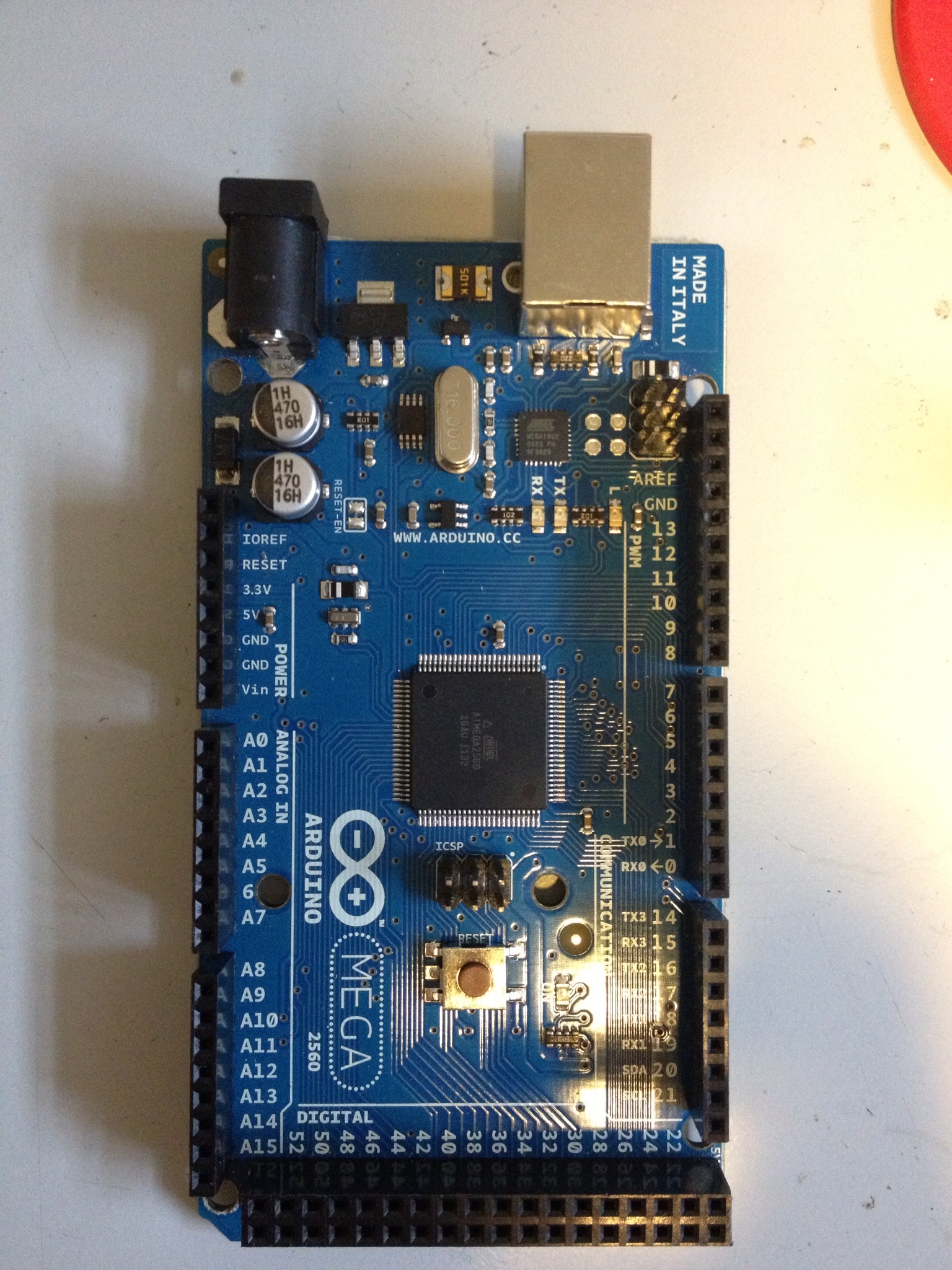
Now before you build the project let me talk about the Arduino.
On the either side of the Arduino you see two rows of headers. This are where you will insert components and interface with the board. On the right side of my board you will see the digital pins.
Digital pins are where you can light up a LED, or detect if a button is being pressed. Because of that, you will focus on the digital pins for this tutorial.
You will also see pins which allow you to reset the board. You can also power the board from some of these pins as well as get 3V and 5V from these pins.
And finally at the top of my board you see two jacks. One for the USB cable and another for power. You can use USB to power your arduino so there is no need to get a power supply for this tutorial.
The Build
Now let’s start building! It shouldn’t take long – this is one of the easiest circuits you will ever make.
How a pull-up resistor works.

A pull-up resistor, similar to a pull-down resistor, is a way to direct electricity or a signal to a specific location depending on certain conditions. The main thing to remember is that electricity wants to go to ground as fast as possible. If you look at the diagram, you can see a basic schematic on how this works.
In our case with the button, you have voltage that can take two paths. The first path is from the voltage source to the digital pin which would result in a high signal or it can travel to ground via button which would result the microcontroller to read a low signal.
When the button is open (not pressed), the voltage signal will go to the microcontroller because it is the quickest path to ground. When the button is closed (pressed), the signal will be pulled to ground.
I’ll show you two ways – one without a breadboard, and one with.
Without a breadboard
Put one wire from the button into pin 2 and the other wire from the button into the ground pin.
Next put the longer side (the positive, anode lead) of the LED into pin 13 and the shorter side (cathode, negative lead) into ground.
That’s it! Let’s get coding.


With a breadboard
If you prefer using a breadboard (like the one that comes with the Sparkfun Inventor’s Kit), here’s how to get it working with that.
- Connect a wire from the 5V pin on your Arduino to the + column, row 30 on your breadboard.
- Connect a wire from the Ground pin on your Arduino to the – column, row 29 on your breadboard.
- Put the long leg of your LED in column F, row 9 on your breadboard, and the short leg in column F, row 10.
- Place a 330 ohn resistor between column j, row 10 on your breadboard to column -, row 10 on your breadboard.
- Connecta wire from J9 to digital pin 3 on your Arduino.
- Place the button somewhere on your breadboard (I put the top legs on column 15). Connect one side of the button to ground (the – column) and one to pin 3 on your Arduino.
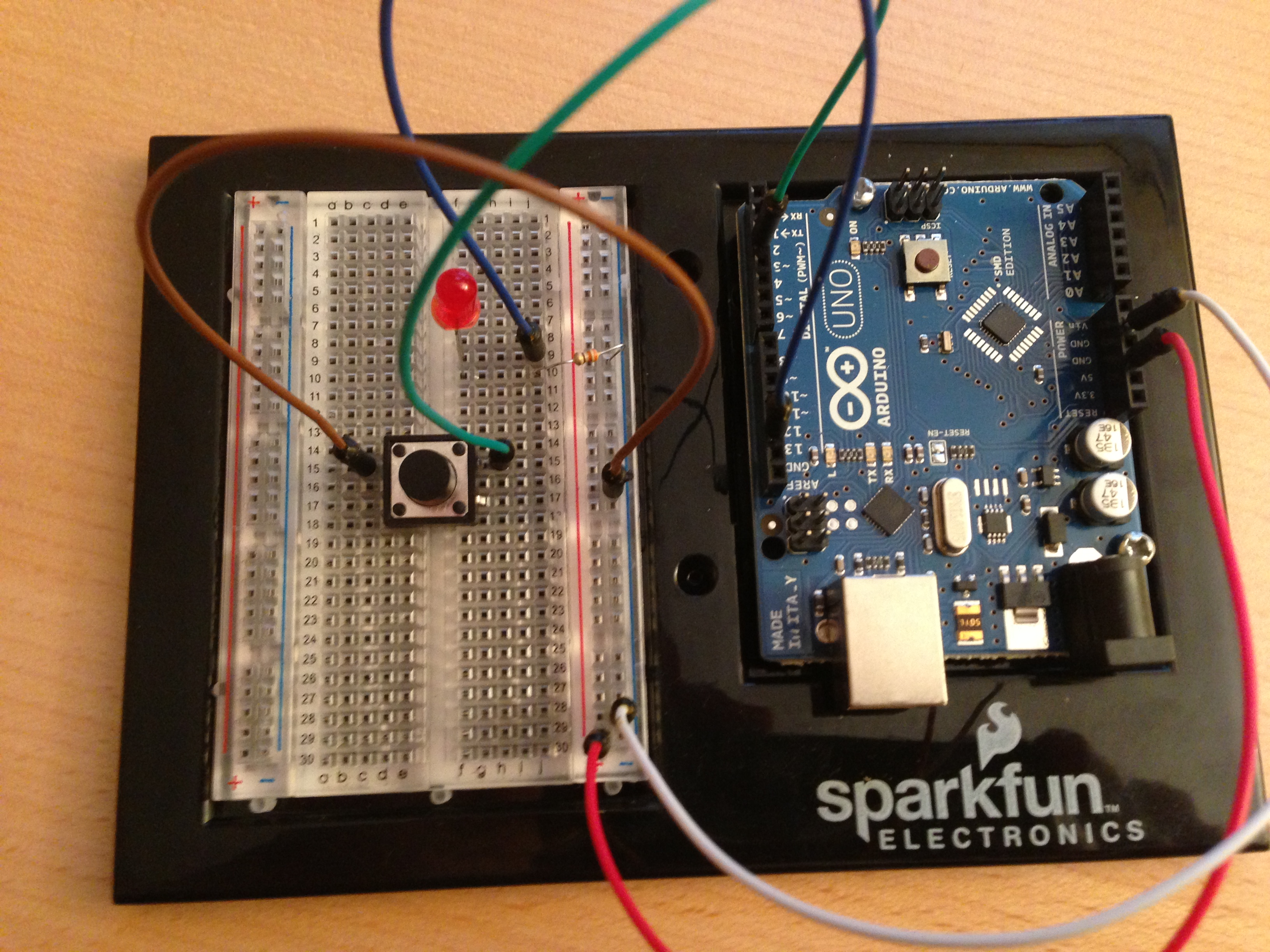
You’re done!
How ‘Bout Some Code
Download the Arduino IDE from the Arduino website – it’s free and easy to install.
Once you’ve installed the IDE, launch it and go to File\New to create a new Arduino sketch (program).
For those who are worried about the difficulty of arduino programming, don’t be! It is quite easy and the platform is used by many people that are willing to help others through forums and tutorials, like this one.
At the beginning of most Arduino sketches, you will find your declarations. These are where you give variables names and values.
Let’s start off by declaring the pin numbers for the components that you’ve hooked up to the Arduino. Keep in mind that the arduino will not know that these are pins until you tell it so a bit later.
Add this code to your new file:
int buttonInput = 2;
Let’s dissect this bit of code. You start of by typing in “int”. This stands for integer which means a number. You next give our button a name. In this case it is buttonInput. Finally you type in “= 2;” to give buttonInput the value of 2, which is the pin number that you hooked the button into.
Let’s do this for our LED. Add the following lines next:
int lightOutput = 13;
int buttonState = 0;
The first line of code is same as you did for the button, except you’re listing the pin number that the LED is hooked into.
You’ll use the buttonState variable in a bit to check to see if the button is currently being pressed or not. For now, you set it to 0 (off).
Now let’s tell your Arduino that lightOutput and buttonInput are components plugged into some of the pins on our device. What you are going to do next is write a method called setup, that gets called when your program first starts up. It’s the place you tell Arduino what pins are used for what, or any other thing that requires initial setup.
Let’s try this out. Add the following code to your file next:
void setup() {
    pinMode(lightOutput, OUTPUT);
    pinMode(buttonInput, INPUT);
    digitalWrite(buttonInput, HIGH);
}
That’s cool, but what does it mean? Well pinMode is a function that takes two parameters. One is the name of a variable. In the first line case it is lightOutput which equals 13. The second parameter says whether it’s an input or output variable. You want to be able to set the LED to light up when the button is pressed, so you want output.
The button on the other hand is input – you want to read to see when it’s pressed.
You might wonder about the third line though – why are you writing out HIGH to the buttonInput?
In order to understand this you will have to understand what happens in the digital world. A computer is basically a bunch of switches. You have one’s when a switch is on and a zero for when it is off. When a switch is on, at one, it is in a HIGH state. When it is off, at zero, then it is at a low state.
Basically digitalWrite tells the arduino to send a high signal to the button’s pin. This is enabling a pull-up resistor. When the button is not being pushed it will be at a high state, when it is pulled to ground it will be a low state. This is a bit backwards than what you might think. This is so you can use less parts and you don’t have to worry about adding pull down resisters to your project because a pull-up resistor is built into the Arduino.
Note: To learn more about pull-up resistors, check out the documentation on the Arduino website.
Got that? Cool! What’s next?
Now you need to do some checking on on things. A lot of times in any kind of programming thereare some tasks you need to run constatnly. You need to do them over and over again. Now this may throw you for a loop. Luckily, for tasks such as these, there is a loop method (terrible pun intended).
This method will get automatically called for you over and over again by the Arduino. It’s a perfect chance to check to see if the button is being pressed, and light up the LED if so.
Add the following code to your file next:
void loop() {
    buttonState = digitalRead(buttonInput);
    if (buttonState == HIGH) {
        digitalWrite(lightOutput, LOW);
    } else {
        digitalWrite(lightOutput, HIGH);
    }
}
digitalRead checks to see what the value of buttonInput is at. So if the button is being pressed it will read LOW. If it is not being pressed it will be HIGH.
Similarly, you call digitalWrite to light up the LED (or not) based on whether the button is pressed.
Congratulations, you are done coding! Your finished file should look like this:

Let’s get this onto the Arduino!