Arduino Tutorial: Networked Temperature Sensor with Swift
In this Arduino Tutorial, you’ll work with a temperature sensor and the companion iPhone app in Swift to connect with it! By Tony Dahbura.
Wiring It All Together
First, if you haven’t already, assemble the Arduino UNO and breadboard based on instructions that come from Sparkfun.
Next, look on the bottom of the Ethernet board for the MAC address and write it down, you’ll need to include it in the code you write to control the interface.
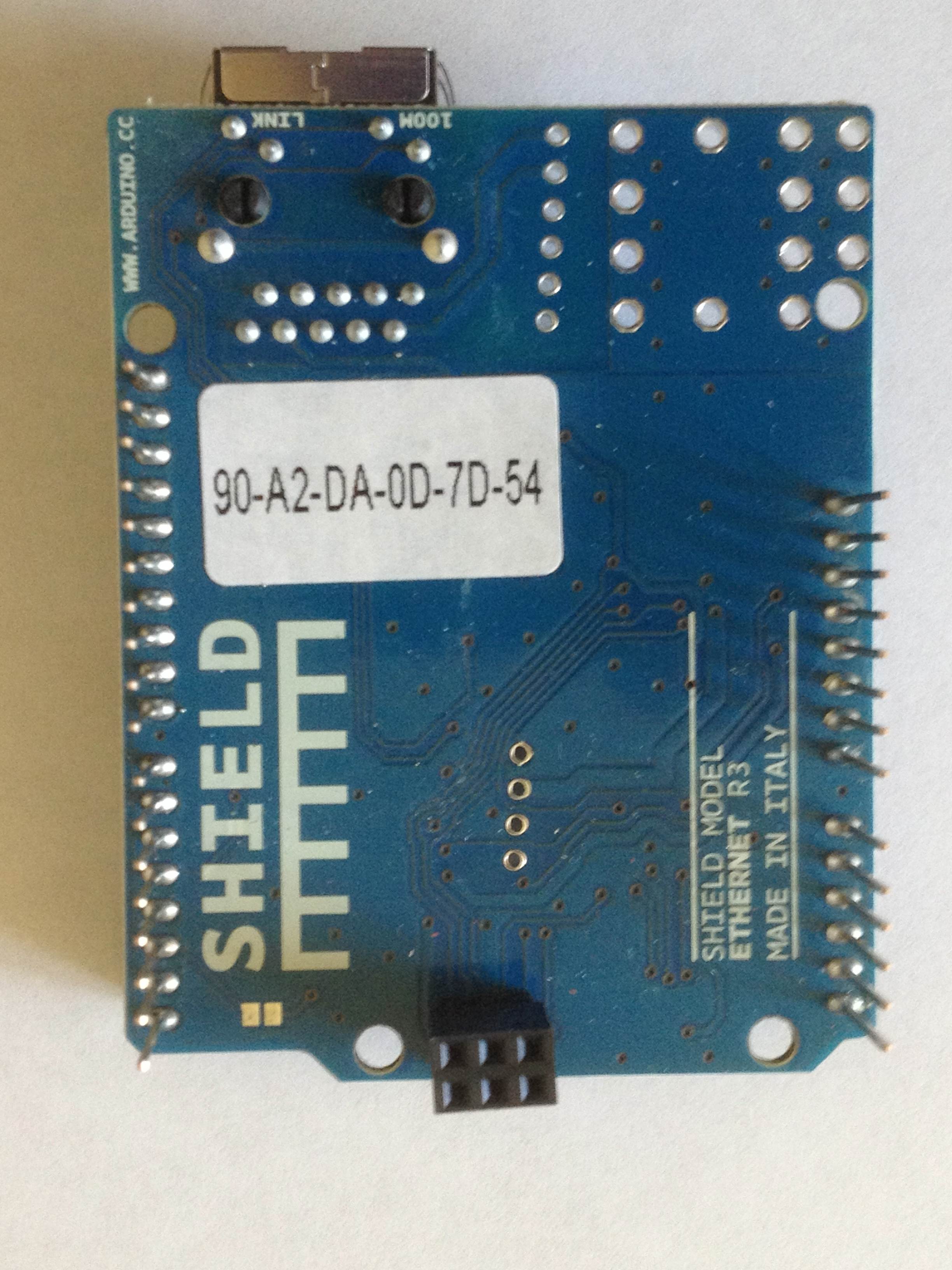
Then plug the Ethernet Shield into the header pins on the Arduino board. Note that there are six pins on the back of the Ethernet Shield that also connect to the UNO board. Slide the board into place carefully and the Ethernet jack should be above the USB connector.
Installing the Grove Shield
You might have initially thought about plugging the Grove Shield in first, then placing the Ethernet Shield on top of that. Unfortunately, this won’t work due to the Grove Shield not passing the 6 pins on the back through to the front.
This brings up an important point regarding Arduino shields: they are not built identically. Many times you need to come up with creative ways to mix and match different shields. The stackable headers lift the boards far enough apart to avoid shorting pins.
Insert the four stackable headers into the header pins on the Ethernet Shield. You need these because the Ethernet Shield’s RJ45 connector is large enough to short out the headers on the Grove Shield (basically, an electric charge might flow from the metal of the RJ45 connector to the Grove Shield, causing major problems!)
Each header matches the pin counts on one of the Ethernet Shield’s headers. When you’re done, your board should look like this:

Carefully place the Grove Shield board in place onto the stackable headers without bending or missing any pins. The Grove Shield has only six pins going into the right and left headers, which have eight on the Ethernet Shield. Align the back pins away from the RJ45 connector and don’t worry about the two missing pins.
After installation, the Grove Shield should look like this:

Note the two missing pins on the side facing you (indicated by the arrows) and on the opposite side. All other pins should be seated inside of the headers.
Now you will wire in the LED as a status indicator. Besides, what’s an electronics project without some blinking LEDs? :]
- Connect a blue wire to one of the connectors in the blue row on the breadboard.
- Connect an orange wire to row J, column 16 on your breadboard.
- Connect a 330-ohm resistor (orange/orange/brown) to row J, column 17. Connect the other end of the resistor in the blue row for column J.
- Connect the longer lead (+) of a green LED to row F, column 16 and the shorter lead (-) to row F, column 17.
Once you’ve completed the above, your breadboard should look like this:

Looking down on the Grove Shield, connect your two LED wires. Plug the blue (GND) wire into the fifth pin from the front on the right side. Insert the orange wire into the ninth pin from the front on the left side (the first pin in the second connector).

Plug the two temperature sensors into the jacks labeled D5 and D6, respectively. The connectors will only go in one way. The jacks are circled in the image below.

As I mentioned in the beginning of this tutorial, you’ll need a port available on your network switch or wireless hub and to be close enough to run a cable from it to your Ethernet shield. So go ahead and run an Ethernet cable from the RJ-45 jack on the Ethernet Shield to your switch or hub.
Connect the USB cable to power and program the circuit into your computer. You may be prompted by your Mac about a new network interface, just click Cancel.
Talking to the Network
Let’s get this circuit talking to your network!
In the downloads folder are various sketch programs to assist. Find the LEDBlinkAndEthernetStarter folder and open LEDBlinkAndEthernetStarter.ino. The file will open in the Arduino IDE and you’ll see this starter code:
#include <SPI.h>
#include <Ethernet.h>

const int ledPin = 7;  //1
byte mac[] = { 0x90, 0xA2, 0xDA, 0x0D, 0x7D, 0x54 };  //2

EthernetServer server(80);  //3
Here’s what’s going on in this starter sketch:
- The line that declares the pin of your status LED.
- This refers to the MAC address you recorded earlier, which is unique to your Ethernet Shield. Replace this value shown with your value.
- Here you create a server object and instruct it to listen on port 80.
A server object? On a microcontroller? Yes, most libraries for the Arduino are written in C++. If you’re curious about how it works, you can peruse the source where you installed the other libraries earlier – look for the folder called Ethernet.
Note: If you would like to review the APIs for the included libraries with the Arduino IDE you can get to them here.
Select File/Upload to compile and load your code into the Arduino.
Once it’s done, select Tools/Serial Monitor and make sure the window has a baud rate of 9600. You should see some messages coming into the window as the system executes the code:

Note: If you do not have DHCP services on your network, you can assign an IP address to the server using the following code right after the line declaring your MAC address:
Then replace Ethernet.begin(mac) with this:
IPAddress ip(192,168,1, 121); //pick some value on your network
Ethernet.begin(mac, ip);
IPAddress ip(192,168,1, 121); //pick some value on your network
Ethernet.begin(mac, ip);
If your LED didn’t come on briefly and then turn out, there could be a few problems :
- You may have the wires in the wrong header pins. Double check the pictures above.
- Make sure that all of the pins for the Grove Sheild and stackable headers are in their slots, and that none are bent (missing their slots).
- You might not have pushed the Grove Shield or Stackable Headers down firmly enough.
If you aren’t sure if they are connected correctly, open the TestLEDOnPin7 sketch in the downloads folder and upload it. The LED should blink as before.
If the LED keeps blinking it means you could not get an IP address correctly. Check your MAC address values and/or router settings.
Whoohoo! You have all of the pieces in place to start reading the temperatures.